

Bone screw and bone lamella structure
A bone screw and bone plate technology, applied in the direction of outer plate, internal bone synthesis, internal fixator, etc., can solve the problems of poor fixation effect, subsidence of femoral head, screw passing out of femoral head, etc., so as to reduce subsidence of femoral head and facilitate The effect of installation
- Summary
- Abstract
- Description
- Claims
- Application Information
AI Technical Summary
Problems solved by technology
Method used
Image

Examples
Embodiment 1
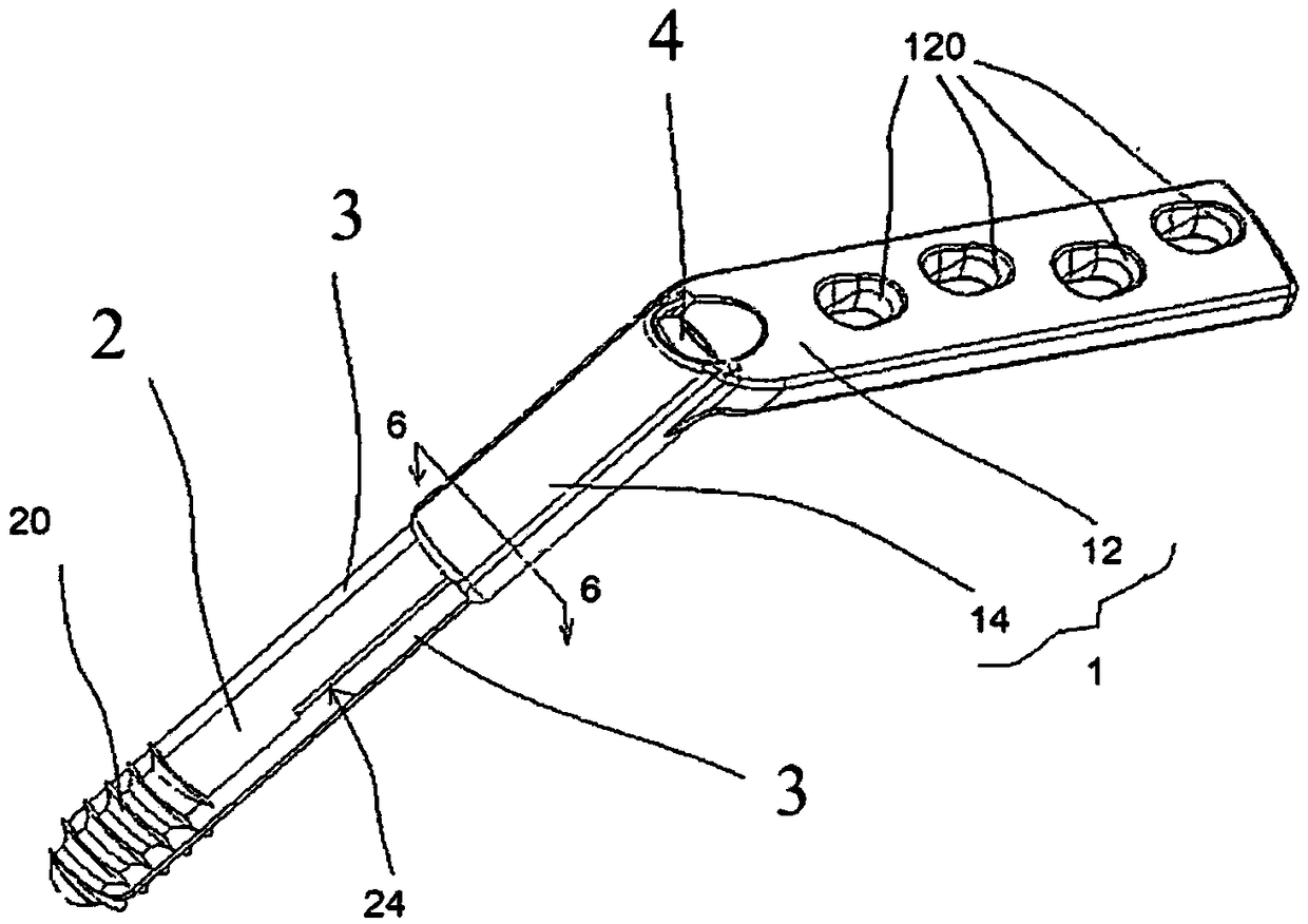
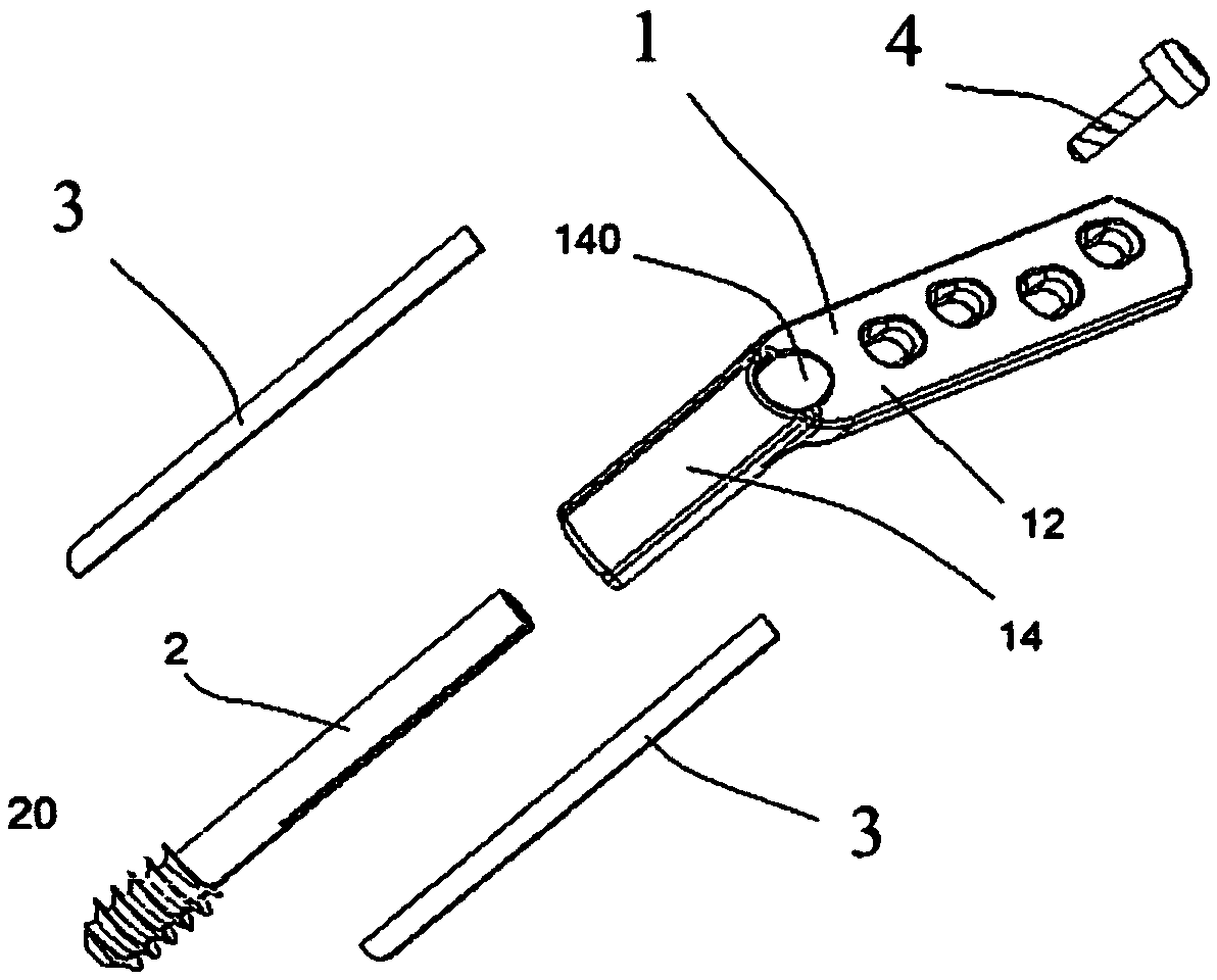
[0028] Embodiment 1, a combination structure of a dynamic bone screw and a bone plate for reduction of a femoral head fracture, including a bone plate body 1 , a slotted bone screw 2 , two resistance blades 3 and a fixing screw 4 . ,
[0029] Such as figure 1 , as shown in 2, 5, and 6, the bone plate body 1 has a joint part 12, and its inner side is a concave arc surface, so that when it is attached to the femur, the contact area between the two can be increased; four perforations 120 pass through the joint part The inner and outer sides of 12 are separated by an appropriate distance; the extension part 14 is a tubular shape with an appropriate length, and the outer edge of its outer end is connected to the upper end of the joint part 12, and the long axis direction of the two is clamped by 120° to 140°. angle, so that the bone plate body 1 is bent; the inner diameter of the shaft hole 140 inside the extension part 14 adjacent to the outer end of the joint part 12 is larger t...
Embodiment 2
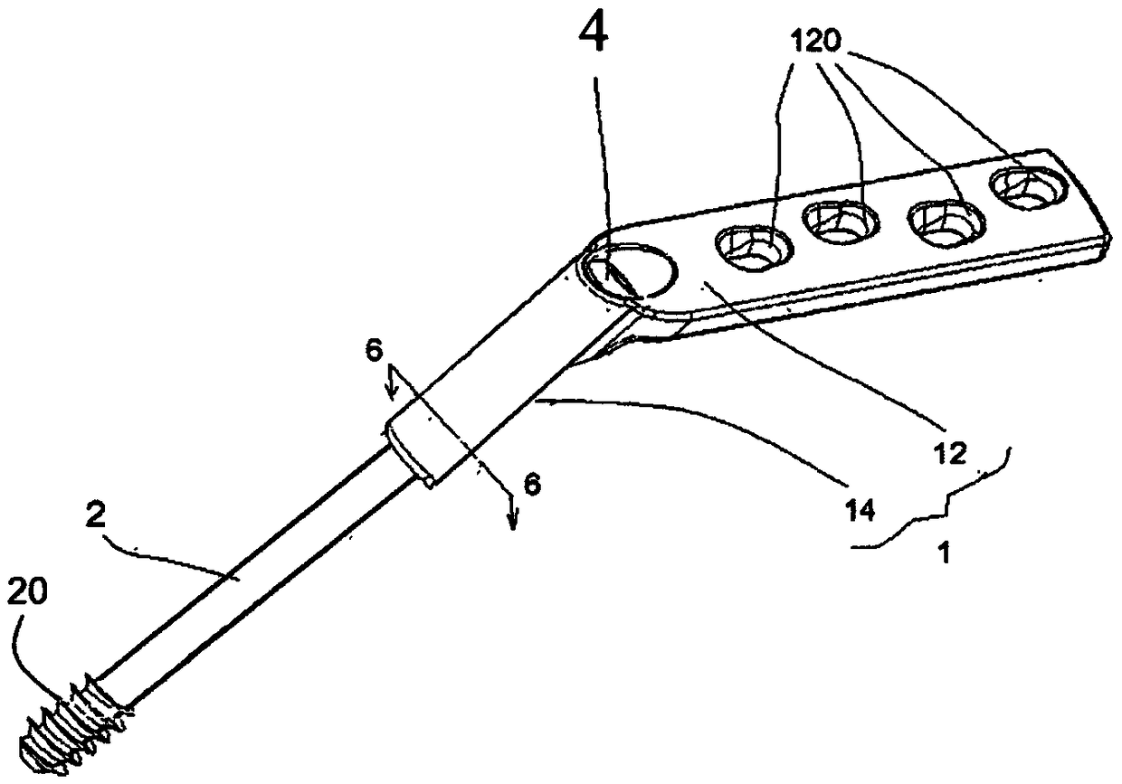
[0039] Embodiment two, such as image 3 As shown in , 4 and 9, the resistance blade 3 shown can be eliminated, leaving only the threaded structure, or the resistance blade 3 does not protrude from the shaft hole 140 .
Embodiment 3
[0040] Embodiment three, such as Figure 10 As shown, a screw structure can also be added on the outer side of the resistance blade 3, as long as the contact area between the dynamic bone screw and the bone plate structure and the femoral head can be increased and the fixation effect can be enhanced to achieve the purpose of the present invention, all belong to this creation. category.
PUM
 Abstract
Description
Claims
Application Information