Changeable confluence area marking line of expressway ramp confluence area and setting method thereof

A technology for expressways and merging areas, applied in road signs, roads, roads, etc., can solve the problems of excessive speed difference between ramp vehicles and main line vehicles, and increase the rational layout of traffic facilities control, so as to ensure safety and reduce traffic. Accidents, the effect of improving safety

Active Publication Date: 2018-11-20
SOUTHEAST UNIV
View PDF4 Cites 12 Cited by
  • Summary
  • Abstract
  • Description
  • Claims
  • Application Information

AI Technical Summary

Problems solved by technology

Since the acceleration lane and the outermost lane of the main line are all white dotted lines that can be crossed, the choice of the merging point for ramp vehicles depends entirely on the driver's own judgment. Vehicles entering from the ramp often merge in advance under the condition of insufficient acceleration. The main line, so that the speed difference between the ramp vehicle and the main line vehicle is too large, and then cause traffic accidents
At the same time, when the speed and traffic volume of the traffic flow change, the lengths that the ramp vehicles need to travel to merge into the main line are also different. This sets up a lot of obstacles for the reasonable arrangement of the expressway ramp merge, and it is impossible to merge on all expressways. Districts use the same model and type of confluence markings, which adds a lot of difficulty to the rational layout of traffic facility control areas

Method used


Image

  • Changeable confluence area marking line of expressway ramp confluence area and setting method thereof
  • Changeable confluence area marking line of expressway ramp confluence area and setting method thereof
  • Changeable confluence area marking line of expressway ramp confluence area and setting method thereof

Examples


Embodiment 1

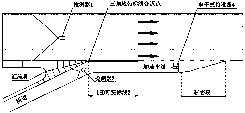
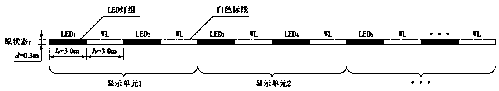
[0035] Such as figure 1 As shown, a variable merging marking in the ramp merge area of ​​the expressway is located at the boundary between the acceleration lane and the outermost lane of the main line in the merge area of ​​the expressway ramp, and undertakes the function of the lane dividing line between the outermost lane of the main line and the acceleration lane. The confluence point is the starting point, including LED light groups arranged at intervals, and white lines are set in the blank area between the light groups, such as figure 2 As shown, the LED light group is black when it is in standby, and it is white when it is working. When the LED light group is working, the solid white marking line and the LED light group in the working area together form a white solid line. At this time, it means that vehicles on the ramp cannot cross the same direction. The dividing line of the lane can only continue to drive forward in the ramp; when the LED lights are on standby, the...

Embodiment 2

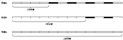
[0040] The difference between this embodiment and Embodiment 1 is that the LED light group constitutes at least one display unit, and each display unit independently selects work or standby, that is, a complete merging marking line in a certain ramp merging area of ​​the expressway, According to the independent work of each display unit, it can be divided into part of white solid line or part of white dotted line, such as image 3 As shown, every two LED light groups form a display unit, assuming that the length of each LED light group is 3m, if only the LED light group in the first display unit starts to work, and the other light groups are on standby, then as follows image 3 When state A occurs, a 12m-long continuous white solid merging line is displayed, and the part of the merging area that cannot cross the dividing line of the same direction lane is 12m long, and vehicles are prohibited from entering the main line traffic through this part ; If there are two consecutive ...

Embodiment 3

[0043] A method for setting variable merging markings in the merging area of ​​an expressway ramp. In actual use, when vehicles on the ramp are not allowed to merge due to traffic flow or speed restrictions, the focus of setting the merging markings is mainly on the white line and How to determine the total length of the solid line composed of LED lamp groups, that is, the length that cannot cross the white solid line in theory, is as follows:

[0044] First, it is necessary to determine the length required for vehicles in the merging area to accelerate to the minimum merging speed. The calculation formula is as follows:

[0045]

[0046] where v c is the minimum confluence velocity in the confluence area; v r is the average running speed of ramp traffic; a is the average acceleration of ramp cars when the slope is 0, generally 0.8-1.2m / s 2 ; i is the slope; g is the acceleration due to gravity.

[0047] Furthermore, to calculate the length required for the vehicle mergi...


PUM


Abstract

The invention discloses a changeable confluence area marking line of an expressway ramp confluence area and a setting method thereof. An LED changeable marking line arranged on the boundary portion ofan acceleration lane and the outermost side lane of a main line in the confluence area is utilized, according to flow and speed combinations of different traffic flows of the main line and ramp traffic, the length of the lane line which cannot be crossed in the same direction can be dynamically adjusted, therefore it is ensured as far as possible that vehicles in the ramp can avoid the areas which are not suitable for confluence, the speed difference between traffic flow of the main line and the vehicles needing to converge in the ramp is reduced, and the safety of the confluence area is improved; in addition, according to the length required by vehicles in the confluence area speeding up to the lowest converging speed and the length required by the vehicle converging process, the lengthof the solid white line which cannot be crossed theoretically is determined, that is, the total length of the solid line composed of a white line and an LED lamp set is determined, working combinations of LED lamp set displaying units and the white line are flexibly matched, so that the marking line adapts to highway types of different structures, the flexibility is better, and the application range is wider.

Description

[0001] Field [0002] The invention belongs to the field of traffic control facilities, and in particular relates to a variable merging marking in a ramp merging area of ​​an expressway and a setting method thereof. Background technique [0003] Since the reform and opening up, the rapid increase in the scale of expressways has greatly supported the rapid development of China's economy, but the traffic safety situation of expressways is not optimistic. The highway ramp merge area mainly includes two types: the connecting part of the ordinary road and the expressway and the connecting part of the expressway interchange. The merging behavior of vehicles in this area has a great impact on the safe operation of traffic. Acceleration, deceleration, lane change and other behaviors of the vehicle in this area may easily cause the driver to make mistakes in judgment and operation, thus leading to traffic accidents. [0004] In the domestic regulations on traffic markings, there is no...

Claims


Application Information

Patent Timeline
Patent Type & Authority Applications(China)
IPC IPC(8): E01F9/582
CPCE01F9/582
Inventor 项乔君郑康康郑展骥禹奥业徐浠鹏甘婧
Owner SOUTHEAST UNIV
Why Eureka
Try Eureka