Double clutch

A dual-clutch and clutch body technology, applied in the field of clutches, can solve problems such as the inability to arbitrarily increase the motion output shaft, the use of torque, the lack of installation space, the increase in cost and the use of power consumption

Pending Publication Date: 2018-11-20
合肥研新离合器有限公司
View PDF0 Cites 0 Cited by
  • Summary
  • Abstract
  • Description
  • Claims
  • Application Information

AI Technical Summary

Problems solved by technology

[0002] In the design of the transmission function of automation equipment, in order to realize the interval and waiting function between each section, generally each section must have a motor, and sometimes in order to achieve uniform speed start and stop, it is also necessary to equip each motor with a frequency converter on the circuit In this way, the cost and power consumption are increased; with the development of technology, electromagnetic clutches appear, but this product has defects in the use of torque and installation space.
Moreover, the existing clutch structure is stable, and it is impossible to increase the motion output shaft at will

Method used


Image

  • Double clutch
  • Double clutch
  • Double clutch

Examples


Embodiment 1

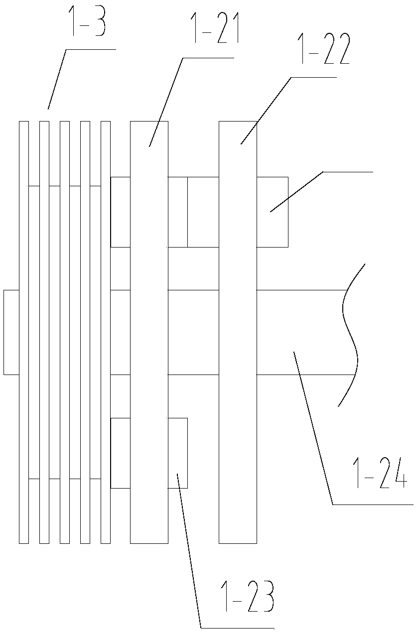
[0030]In this embodiment, the pressure plate 1-2 is composed of a moving plate 1-21 and a fixed plate 1-22, the moving plate 1-21 is set on the input shaft 1-1 in a linear motion, and the fixed plate 1-22 is set on the The input shaft 1-1 rotates following the input shaft 1-1. That is, the fixed disk 1-22 is fixedly connected or splined with the input shaft 1-1, and the fixed disk 1-22 is relatively stationary relative to the input shaft 1-1 in the axial direction. The moving plate 1-21 is provided with a plurality of first through holes distributed on the concentric circles of the moving plate 1-21. The fixed plate 1-22 is provided with at least one second through hole, and the second through hole is located on a circle whose axis coincides with the axis of the fixed plate 1-22 and whose radius is equal to the radius of the circle where the first through holes are located. A first gear 1-23 is rotatably installed in each first through hole, and the rotating shaft of the firs...

Embodiment 2

[0032] In this embodiment, the pressure plate 1-2 includes a first disc 1-2A, a second disc 1-2B and a third disc 1-2C which are sequentially sleeved on the input shaft 1-1. The second disc 1-2B is connected to the input shaft 1-1, and the second disc 1-2B is provided with at least one shaft that runs through the second disc 1-2B and whose axis coincides with the radial direction of the second disc 1-2B. Turn gear 1-2D. The first disc 1-2A is fixedly installed, the third disc 1-2C is rotatably installed and connected with the smooth surface of the input shaft 1-1, and the side of the first disc 1-2A facing the second disc 1-2B is provided with An annular tooth portion 1-2E meshing with the rotating gear 1-2D and located concentrically on the first disc 1-2A. The side of the third disk 1-2C facing the second disk 1-2B is provided with a fan-shaped tooth portion 1-2F meshed with the rotating gear 1-2D, and the fan-shaped tooth portion 1-2F passes through the third disk 1-2C Th...


PUM


Abstract

The invention discloses a double clutch. The double clutch comprises a shell, a first clutch mechanism and a second clutch mechanism, and the first clutch mechanism and the second clutch mechanism aremounted in the shell. The first clutch mechanism comprises an input shaft, a pressure plate, a clutch body, a driving wheel and a first output shaft, and the input shaft and the first output shaft extend out of the shell. The second clutch mechanism comprises a second output shaft, an eccentric rotation wheel, a driven wheel, a connecting rod, a sliding body, an electromagnet and a belt. According to the double clutch, in a state of joint of the second clutch mechanism, the second output shaft and the driven wheel rotate synchronously to realize double-circuit driving. Through the cooperationof the first clutch mechanism and the second clutch mechanism, and double-driving control can be realized to optionally switch between one-way movement output and double-way movement output.

Description

technical field [0001] The invention relates to the technical field of clutches, in particular to a double clutch. Background technique [0002] In the design of the transmission function of automation equipment, in order to realize the interval and waiting function between each section, generally each section must have a motor, and sometimes in order to realize uniform speed start and stop, it is also necessary to equip each motor with a frequency converter on the circuit In this way, the cost and power consumption are increased; with the development of technology, electromagnetic clutches appear, but this product has defects in the use of torque and installation space. Moreover, the existing clutch structure is stable, and it is impossible to increase the motion output shaft at will. Contents of the invention [0003] Based on the technical problems existing in the background technology, the present invention proposes a double clutch. [0004] A double clutch proposed ...

Claims


Application Information

Patent Timeline
IPC IPC(8): F16D21/00
CPCF16D21/00
Inventor 陈必伟
Owner 合肥研新离合器有限公司
Why Eureka
Try Eureka