Novel cross shaft detection device

A detection device and cross-axis technology, which is applied in the direction of measuring devices, mechanical measuring devices, and mechanical devices, etc., can solve the problems of low detection efficiency and inability to adapt to automated production, and achieve the effect of improving efficiency and positioning accuracy

Pending Publication Date: 2018-11-20
南京埃斯顿智能系统工程有限公司
View PDF7 Cites 0 Cited by
  • Summary
  • Abstract
  • Description
  • Claims
  • Application Information

AI Technical Summary

Problems solved by technology

[0003] The purpose of the present invention is to provide a new type of cross-axis detection device, which solves the technical defects of manual clamping and calibration of the cross-axis in the prior art, which cannot adapt to automatic production and low detection efficiency.

Method used


Image

  • Novel cross shaft detection device
  • Novel cross shaft detection device
  • Novel cross shaft detection device

Examples


Embodiment 1

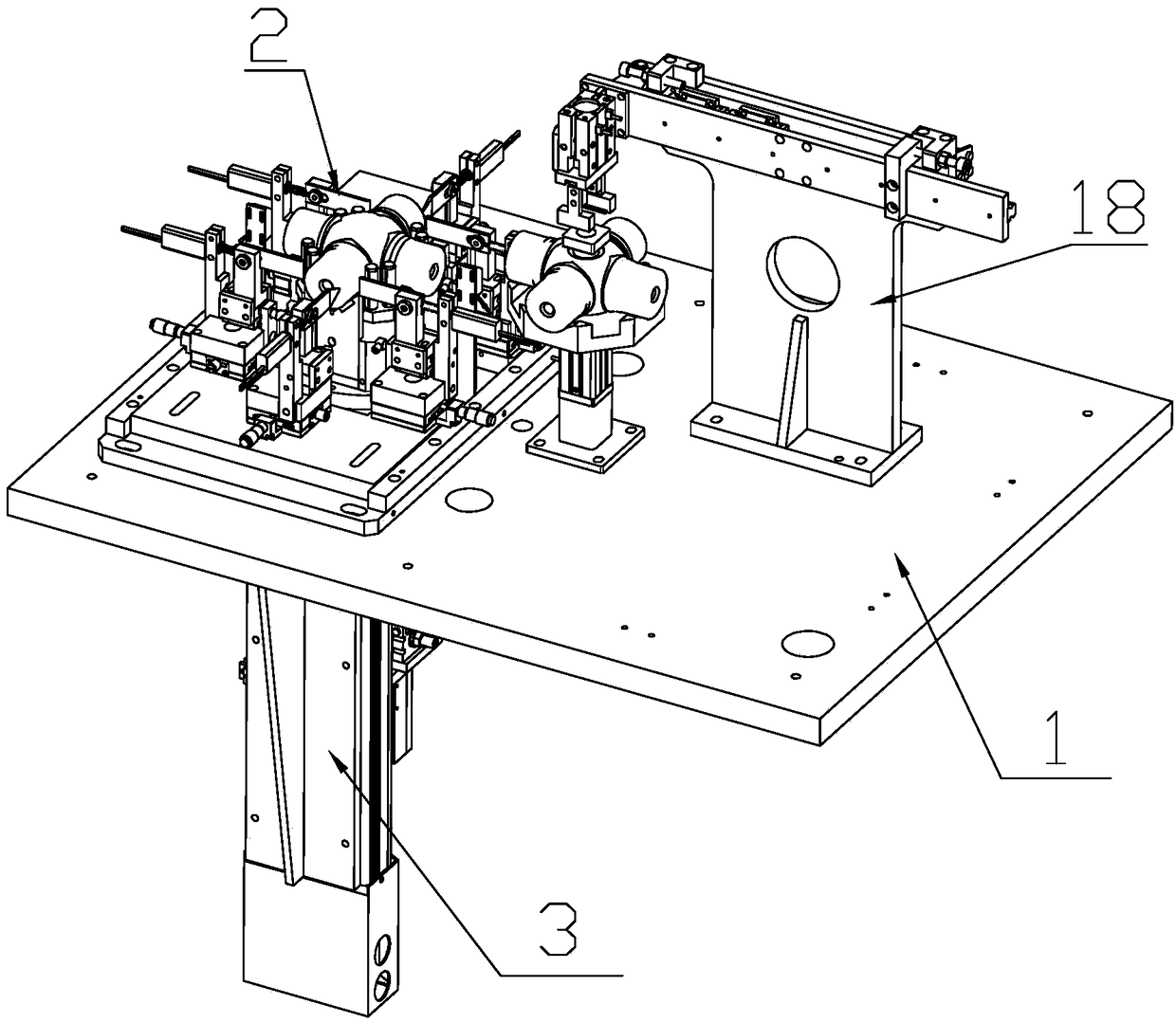
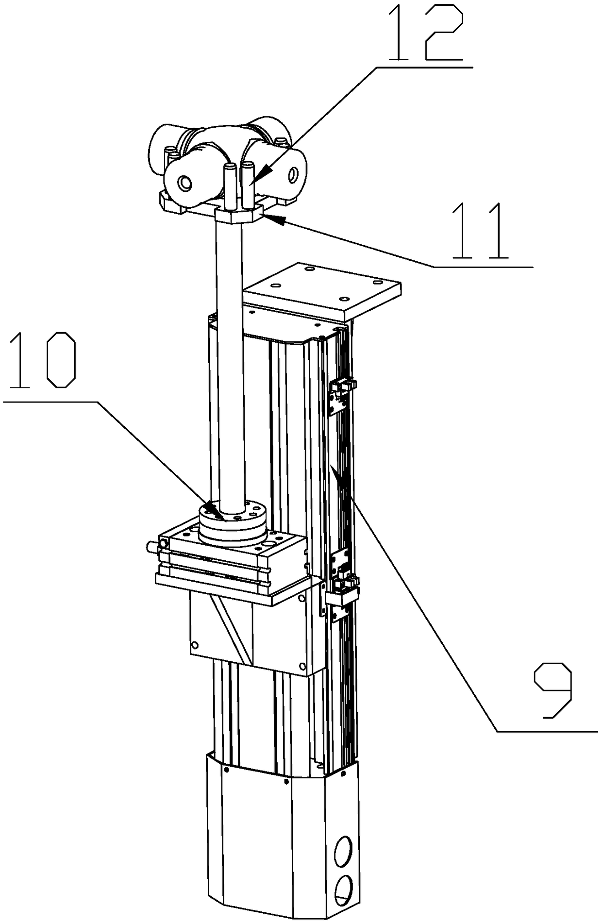
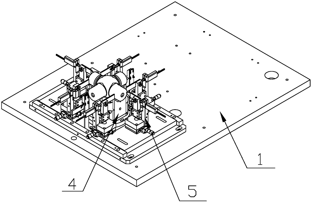
[0019] Such as Figure 1-Figure 4 The new cross axis detection device shown includes a workbench 1 , a detection component 2 arranged on the upper surface of the workbench 1 and a calibration component 3 arranged on the lower surface of the workbench 1 .

[0020] The detection part 2 described in this application includes a support 4 and a plurality of detection parts 5. The workbench 1 is a rectangular plate structure, the bottom of which is supported by a plurality of support columns (not shown in the figure). There is a square through hole (not shown in the figure) running through it on the table 1, and the support 4 includes four support plates (not shown in the figure) vertically arranged around the through hole and of equal height. ), the support plates are connected end to end to form a support frame with a rectangular cross section. The four support plates preferred in this application are of equal length, and the cross section of the support frame is square. There is...

Embodiment 2

[0026] This embodiment is a further improvement made on the basis of embodiment one, compared with embodiment one, as figure 1 and Figure 5 As shown, the present embodiment is also equipped with a clamping part 18 on the upper surface of the workbench 1. The clamping part 18 in this application is installed on the right side of the detection part 2. The clamping part 18 includes a support base plate 19, Sliding plate 20, clamping cylinder 21, finger cylinder 22, telescopic cylinder 23 and a workpiece storage table 25 for placing a standard cross shaft, the bottom of the support base plate 19 is detachably installed on the workbench 1 through a plurality of bolts, The clamping cylinder 21 is installed on the support base plate 19 and the piston rod of the clamping cylinder 21 is arranged horizontally. The piston rod of the clamping cylinder 21 can expand and contract towards the direction of the detection part 2. The slide plate 20 is slidably installed on the support base pla...


PUM


Abstract

The invention discloses a novel cross shaft detection device. The novel cross shaft detection device comprises a work station, a detection part and a calibration part, wherein the detection part comprises a supporting member and multiple detection members, the supporting member comprises four supporting plates, a top portion of the supporting plates is provided with a V-shaped notch matched with the shaft diameter portion of a cross shaft, front and rear portions of a supporting framework are respectively provided with one detection member, left and right sides of the supporting framework arerespectively provided with two detection members, the detection members comprise supporting racks, detection blocks and sensors arranged on the supporting racks in a sliding mode, the detection blockscontact with the sensors, the sensors are arranged at one side away from the supporting framework, the calibration part comprises a sliding table type electric cylinder, a rotary cylinder and a tray,and the tray can move up and down in a through hole. The novel cross shaft detection device is advantaged in that the sensors indirectly contact with the cross shaft, so the sensors are protected from being knocked by the cross shaft; a clamping part and a positioning part are separated, and positioning accuracy is improved; the automatic calibration part is utilized for calibration, and detection efficiency is improved.

Description

technical field [0001] The invention relates to a novel cross axis detection device. Background technique [0002] The cross shaft is one of the commonly used precision components. It can only be used in the factory after passing the test. Specifically, it is the diameter and length of the four shaft diameters of the cross shaft. The existing cross shaft uses a cross shaft detector to detect the length and diameter. The direct contact detection method of the sensor is adopted. The existing detection and positioning method is one-time clamping and positioning, which introduces errors in the clamping system. The current detection system calibration adopts manual clamping calibration, which cannot adapt to automatic production, and the detection efficiency is low. Contents of the invention [0003] The purpose of the present invention is to provide a novel cross-axis detection device, which solves the technical defects in the prior art that the cross-axis adopts manual clam...

Claims


Application Information

Patent Timeline
Patent Type & Authority Applications(China)
IPC IPC(8): G01B5/02G01B5/08
CPCG01B5/02G01B5/08
Inventor 孙小俊黄柯钱浩高强鄢光红朱家洲尹义波
Owner 南京埃斯顿智能系统工程有限公司
Why Eureka
Try Eureka