Lane line identification method based on vehicle-mounted laser radar

A vehicle-mounted lidar, lane line recognition technology, applied in character and pattern recognition, radio wave measurement system, radio wave reflection/re-radiation, etc. Wide-ranging, high-resolution effects

Active Publication Date: 2018-11-20
STATE GRID CORP OF CHINA +1
View PDF3 Cites 1 Cited by
  • Summary
  • Abstract
  • Description
  • Claims
  • Application Information

AI Technical Summary

Problems solved by technology

[0005] The invention uses a laser radar sensor for lane line recognition, which solves the problem that traditional cameras cannot recognize lane lines under poor lighting conditions such as night and fog

Method used


Image

  • Lane line identification method based on vehicle-mounted laser radar
  • Lane line identification method based on vehicle-mounted laser radar
  • Lane line identification method based on vehicle-mounted laser radar

Examples


Embodiment Construction

[0042] Below in conjunction with accompanying drawing, the present invention will be further described:

[0043] The lane line recognition method based on vehicle lidar, the steps are as follows:

[0044] 1. Read the road point cloud data in the middle of curb (curb is the curb):

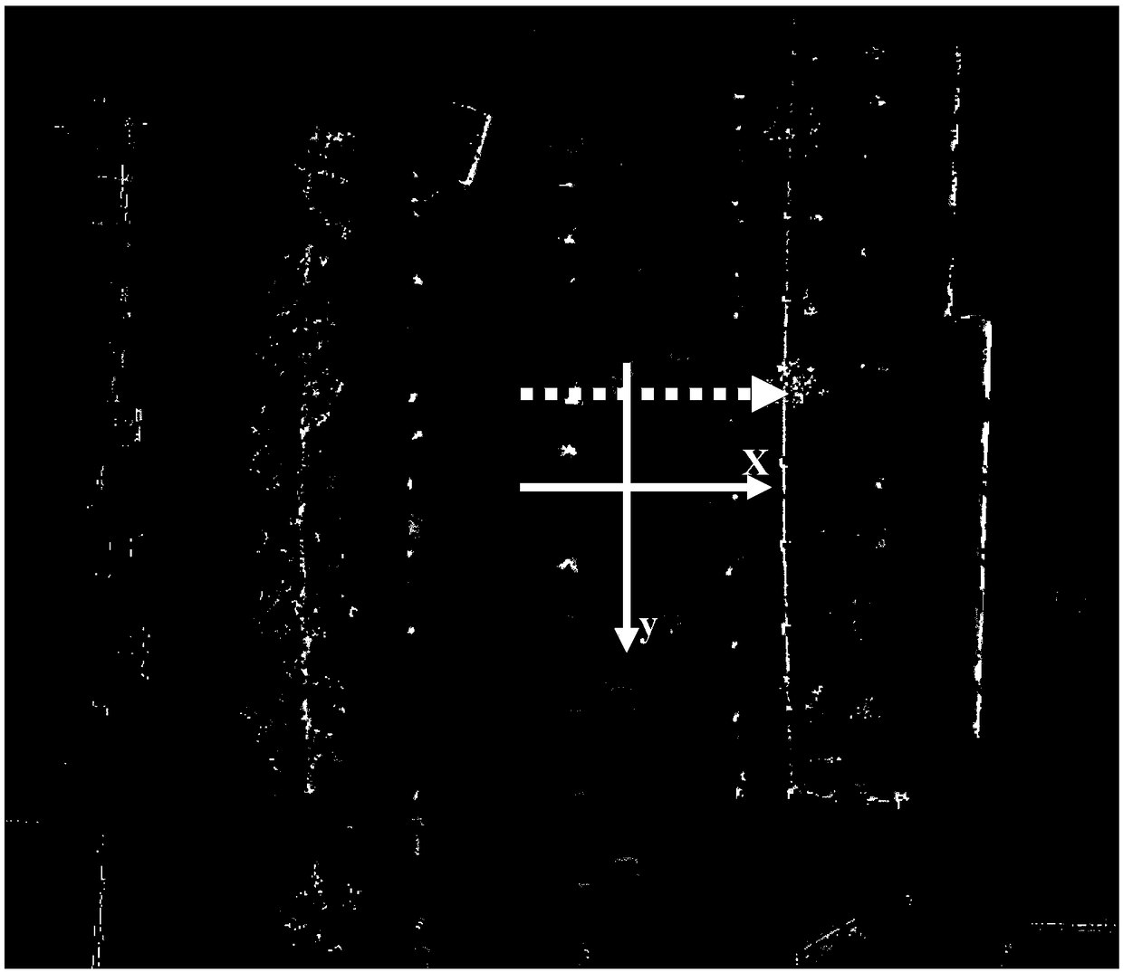
[0045] In this embodiment, a 32-line laser radar sensor is used, and the sensor is installed vertically on the roof of the vehicle to obtain the environmental point cloud data of the road and its surroundings;

[0046] (1) First, in order to limit the road analysis area, use the least squares algorithm to fit the functional relationship y of the left and right curb respectively l =a l x l +b l and y r =a r x r +b r , where y l Represents the ordinate value of the curb point cloud on the left, x l Represents the abscissa value of the curb point cloud on the left, a l is the coefficient of the curb function on the left, b l is the intercept of curb function on the left, y r Represents the...


PUM


Abstract

The invention relates to a lane line identification method based on a vehicle-mounted laser radar, and belongs to the field of mode identification of automatic driving. The method comprises the following steps of 1) reading road point cloud data in curb, 2) ordering, 3) filtering a mean value, 4) searching for a peak value, 5) screening height information of lane lines, and 6) screening a peak value by combining different lines. The vehicles lines in front of and behind a vehicle are identified. The problem that the lane lines cannot be identified by a traditional camera in low illumination conditions as the night or foggy days is solved.

Description

technical field [0001] The invention belongs to the field of automatic driving pattern recognition, and relates to laser radar point cloud data processing and recognition methods. Background technique [0002] Lane line detection plays a key role in the intelligent vehicle auxiliary safety system. The lane departure warning system has a wide range of applications in the lane keeping assist system and the lane changing assist system; at the same time, the lane line detection is the basis of the intelligent vehicle automatic navigation system. The optimal driving path for vehicle automatic navigation needs to be planned based on the acquired road environment information, and lane line detection is very important in specific lane driving. [0003] The basic principle of lane line detection is to use sensors to obtain road and surrounding environment information, and then obtain the specific location of the lane line through complex analysis, and finally play a role in the vehic...

Claims


Application Information

Patent Timeline
Patent Type & Authority Applications(China)
IPC IPC(8): G01S13/88G01S13/91G06K9/00
CPCG01S13/88G01S13/91G06V20/588
Inventor 李桐刘扬陈得丰杨智斌耿洪碧李欢任帅
Owner STATE GRID CORP OF CHINA
Why Eureka
Try Eureka