
Pipe coiling machine with protective pad

A technology of coiling machine and protective pad, applied in mechanical equipment, belt/chain/gear, transmission parts, etc., can solve the problems of inconvenient to add lubricating oil, no installation of casing, inconvenient installation of pressure roller, etc.

Inactive Publication Date: 2018-11-23
丽水新贝蕾科技有限公司
View PDF0 Cites 1 Cited by
  • Summary
  • Abstract
  • Description
  • Claims
  • Application Information

AI Technical Summary

Problems solved by technology

[0004] The purpose of the present invention is to provide a pipe reel with a protective pad to solve the above-mentioned problems in the background technology that there is no sleeve installed, the pressure roller is not easy to install, the top ball is not installed, the gear is not easy to rotate after long-term use, and it is not easy to add oil problem

Method used

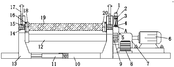

Image

  • Pipe coiling machine with protective pad
  • Pipe coiling machine with protective pad
  • Pipe coiling machine with protective pad

Examples


Embodiment Construction

[0018] The following will clearly and completely describe the technical solutions in the embodiments of the present invention with reference to the accompanying drawings in the embodiments of the present invention. Obviously, the described embodiments are only some, not all, embodiments of the present invention. Based on the embodiments of the present invention, all other embodiments obtained by persons of ordinary skill in the art without making creative efforts belong to the protection scope of the present invention.

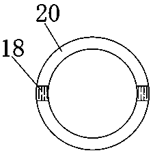
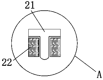
[0019] see Figure 1-4 , the present invention provides the following technical solutions: a pipe coiler with a protective pad, including a pressure roller 19, the outer sides of both ends of the pressure roller 19 are connected to the casing 20 through the clamping block 16, and four clamping blocks 16 are installed in total. And the exteriors of four clamping blocks 16 are all wrapped with cushions, and two sleeve pipes 20 are installed in total, and the ins...


PUM


Abstract

The invention discloses a pipe coiling machine with a protective pad. The pipe coiling machine comprises a compression roller. The outer sides of the two ends of the compression roller are connected with sleeves through clamping blocks correspondingly. The totally four clamping blocks are mounted, and the exteriors of the four clamping blocks are wrapped with soft pads correspondingly. The totallytwo sleeves are mounted, and two first sliding grooves are formed in the two sleeves correspondingly. Second sliding grooves are formed in one sides of the two first sliding grooves correspondingly.One sides of the two sleeves are connected with moving blocks correspondingly. The upper ends of the two moving blocks are fixedly connected with adjusting rods correspondingly. Two gears are mountedin a dust-proof box, and a jacking bead is mounted in an oil layer. Stopping blocks are symmetrically mounted on the two sides of the jacking bead. An oil tank is mounted at the upper end of a first electric telescopic rod. One side of the lower portion of the oil tank is fixedly connected with the oil layer through an oil pipe. The pipe coiling machine is provided with the sleeves, the four clamping blocks all slide into the two second sliding grooves, and thus the problem that the compression roller is inconvenient to mount is avoided.

Description

technical field [0001] The invention belongs to the technical field of coiling machines, and in particular relates to a coiling machine with a protective pad. Background technique [0002] Tube rolling machine, as the name suggests, is a machine that produces paper tubes. The paper tubes produced are used in various industries, such as tubes for fiber industry, tubes for film industry, tubes for printing industry, tubes for paper industry, and tubes for leather industry. , food packaging tubes, construction industry tubes, exhibition industry tubes, etc. There are also various types of tube coilers. The most common tube coilers are spiral coil machines and flat coil coil machines. system, so the program design of the upper computer is more important. The upper computer calculates the coil geometric parameters and process parameters for the input plate and roll paper product parameters according to the calculation model, checks the number of feeds, and finally sends the calcu...

Claims


Application Information

Patent Timeline
Patent Type & Authority Applications(China)
IPC IPC(8): B21D5/14F16H57/04
CPCB21D5/14F16H57/0423
Inventor 唐成晶
Owner 丽水新贝蕾科技有限公司
Learn More