
Brake disc punching auxiliary tool

A technology for auxiliary tooling and brake discs. It is applied in the direction of manufacturing tools, positioning devices, boring/drilling, etc. It can solve problems such as inappropriate drilling positions, easy shaking, and inaccurate prediction of the position of the screw-out point. Achieve the effect of simple and convenient punching operation

Active Publication Date: 2018-11-23
CHERY AUTOMOBILE CO LTD
View PDF5 Cites 1 Cited by
  • Summary
  • Abstract
  • Description
  • Claims
  • Application Information

AI Technical Summary

Problems solved by technology

[0003] The brake disc is round, so it is necessary to drill a hole that runs through both sides at an inclined angle. There are two technical difficulties: 1. The brake disc is difficult to fix, easy to shake, and the drill bit is easy to break during the drilling process; 2. The drill bit is broken from one end. In and out position prediction is inaccurate
[0004] At present, drilling in the industry depends entirely on experience. If the position of the drilling is not suitable, it will be re-drilled with a new disc, resulting in waste of brake discs and low work efficiency. If the drilling position is not accurate, the test results will be inconsistent. deviation

Method used


Image

  • Brake disc punching auxiliary tool
  • Brake disc punching auxiliary tool
  • Brake disc punching auxiliary tool

Examples


Embodiment 1

[0022] This embodiment proposes an auxiliary tool for drilling holes in the brake disc to facilitate the drilling of the brake disc and improve the accuracy of drilling.

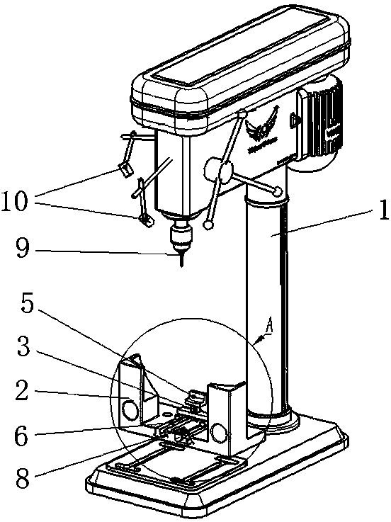
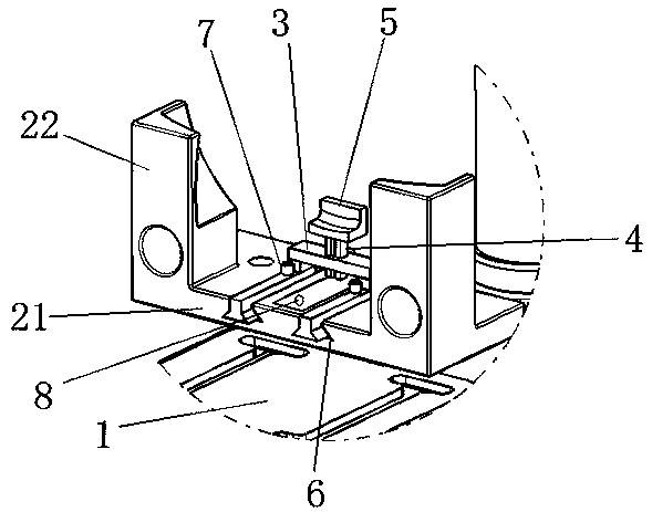
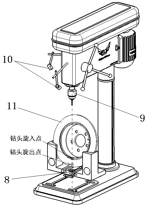
[0023] Such as figure 1 , 2 As shown, the auxiliary tooling for drilling the brake disc in this embodiment includes a bench drill 1 and a brake disc fixing mechanism fixedly installed on the base of the bench drill 1; wherein:

[0024] The brake disc fixing mechanism is composed of the rim support seat 2, the slider 3, and the disc cap support seat. The disc cap support seat is fixedly connected by the lower support rod 4 and the upper disc cap adapter part 5. The part 5 is provided with a curved surface matching the surface of the brake disc cap; the slider 3 is provided with a vertical through hole, and fastening bolts are installed through the hole wall of the vertical through hole, and the support rod 4 Down through the vertical through hole of the slide block 3, the side of the support rod 4 is agains...


PUM


Abstract

The invention aims at providing a brake disc punching auxiliary tool. By means of the brake disc punching auxiliary tool, a brake disc can be conveniently punched, and punching accuracy is improved. The brake disc punching auxiliary tool disclosed by the invention comprises a bench drill and a brake disc fixing mechanism fixedly arranged on a bench drill base, wherein two screwed-in point infraredgenerator are arranged on the sides of a drill bit of the bench drill, a central-axis infrared generator is arranged on the brake disc fixing mechanism, a linear infrared beam upwards sent out by thecentral-axis infrared generator coincides with the central axis of the drill bit, infrared rays emitted out by the two screwed-in point infrared generators are planar linear beams, and the two planarlinear beams intersect with each other at the straight line on which the central axis of the drill bit. The brake disc punching auxiliary tool disclosed by the invention is provided with a rim supporting seat and a disc cap supporting seat, so that brake disc posture can be adjusted according to need; furthermore, a plurality of infrared generators are utilized for accurately locating a screwed-in point and a screwed-out point of the drill bit on the brake disc before drilling; thus, punching operation can be conveniently performed, and the punching operation is simple and convenient and cansucceed in one time.

Description

technical field [0001] The invention belongs to the technical field of automobile chassis brake applications, and in particular relates to the test of automobile brake discs. Background technique [0002] In the braking performance test of passenger cars, it is necessary to drill holes in the brake disc and install thermocouples in the holes. The thermocouple should be installed in the center of the inner and outer friction rings on the friction ring, 0.5mm away from the surface of the brake disc. The installation position of the thermocouple determines the accuracy of the test results, so the requirements for the installation position of the thermocouple are relatively high. [0003] The brake disc is round and needs to drill a hole with an inclined angle that runs through both sides. There are two technical difficulties: 1. The brake disc is difficult to fix, easy to shake, and the drill bit is easy to break during the drilling process; 2. The drill bit is broken from one ...

Claims


Application Information

Patent Timeline
Patent Type & Authority Applications(China)
IPC IPC(8): B23B41/00B23Q3/06B23Q17/24B23Q17/22
CPCB23B41/00B23Q3/062B23Q17/2419
Inventor 方磊徐自明游廷海李彬
Owner CHERY AUTOMOBILE CO LTD
Learn More