Supercharge Your Innovation With Domain-Expert AI Agents!

Edge grinding device for liquid crystal module production

A liquid crystal module and edge grinding technology, which is applied to grinding driving devices, machine tools suitable for grinding workpiece edges, grinding machines, etc., can solve the problems of poor fixation effect of liquid crystal panels, inability to meet mass production, low work efficiency, etc. To achieve the effect of saving manpower, improving fixing effect and preventing pollution

Inactive Publication Date: 2018-11-23
YANCHENG HUAXU OPTOELECTRONICS TECH CO LTD
View PDF0 Cites 10 Cited by
  • Summary
  • Abstract
  • Description
  • Claims
  • Application Information

AI Technical Summary

Benefits of technology

This technology allows for efficient and reliable cutting of lithium ion batteries (LIB). It involves inserting an Liquid Crystalline Display Panel into a special slot that holds it securely while also allowing its movement within this space. By pressing both ends together or moving them up/down, the display pane becomes taller when viewed horizontally compared to traditional methods like holding one side tight against another's edges. To fix the battery panels properly, they are moved vertically onto a guide board beforehand. A rotational driver moves the slides backwards towards each other causing compression force between these components. Grounding wheels roll over the screen to smoother out any roughnesses caused by the saw blade. Dust covers collect dirt particles entering the system where the clean air flows around. Filter removes some harmful substances such as water mist and grit.

Problems solved by technology

This patented technical problem addressed in this patents relates to improving the quality control (QC) performance during manufacturing processes involving liquid crystals displays such as Liquid Crystal Display TFTs or Plasma Displays. Current methods involve manually trimming the cut-edge portions from the screens before assembling them into liquid cryostats. However, current solutions require high labor intensity due to their complexity and lack of efficient operation compared to automated systems like those described earlier.

Method used


Image

  • Edge grinding device for liquid crystal module production
  • Edge grinding device for liquid crystal module production
  • Edge grinding device for liquid crystal module production

Examples


Embodiment Construction

[0018] The specific implementation manners of the present invention will be further described in detail below in conjunction with the accompanying drawings and embodiments. The following examples are used to illustrate the present invention, but are not intended to limit the scope of the present invention.

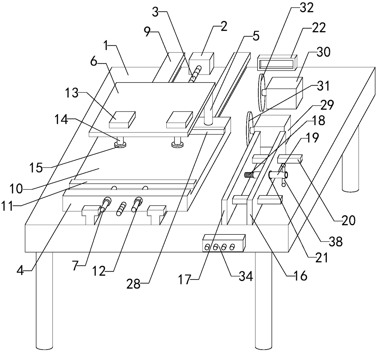
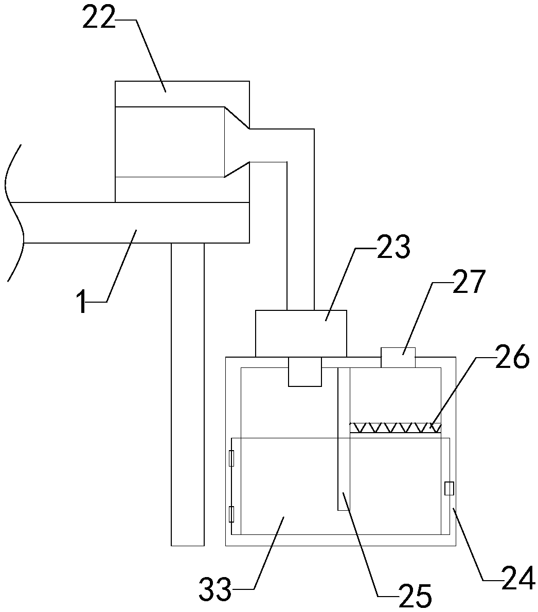
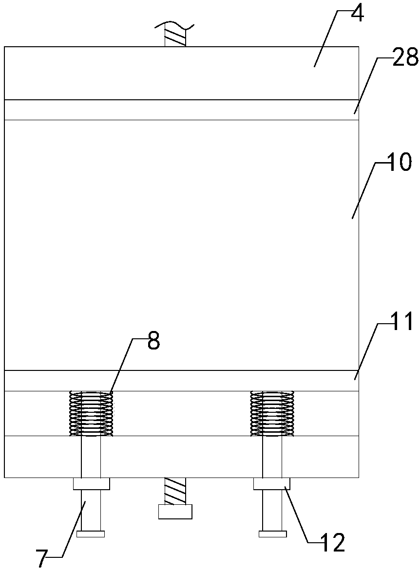
[0019] like Figure 1 to Figure 4As shown, a kind of edging device used for liquid crystal module production of the present invention comprises workbench 1, reciprocating motor 2, lead screw 3, slide table 4, two sets of columns 5, top plate 6, two sets of pull rods 7 and two Set of springs 8, two sets of longitudinal slide rails 9 are arranged on the top of the workbench, and two sets of longitudinal slide grooves are arranged on the bottom of the slide table, the two sets of slide rails are respectively located in the two sets of slide grooves, the slide table can The slide rail slides back and forth, and a threaded hole is provided in the middle of the slide table. The...


PUM


Abstract

The invention relates to the technical field of liquid crystal module processing accessory devices, in particular to an edge grinding device for liquid crystal module production. By the edge grindingdevice, manpower can be saved, working efficiency can be improved, and requirements of mass production can be met; effect of fixing a liquid crystal panel is improved, impact of vibration of the liquid crystal panel on edge grinding effect in the process of edge grinding is prevented, and practicability is improved; chippings generated in the process of edge grinding can be collected and treated,pollution of working environment is prevented, workers are avoided being scratched by glass chippings, potential safety hazards are reduced, and using reliability is improved. The edge grinding devicecomprises a workbench, a reciprocating motor, a screw, a sliding table, uprights, a top plate, pulling rods, springs, sliding rails, a front clamping plate, a limiting block, cylinders, extensible rods, a pressing plate, an edge grinding motor, a fixing plate, a positioning plate, a threaded rod, a threaded pipe, square pipes, a ball bearing, a grinding wheel, a dust suction hood, a centrifugal fan, a dust collection box, a partition, a filter net and an air outgoing pipe, and a rectangular placement groove and a sliding groove are arranged at the top end and the bottom end of the sliding table respectively.

Description


Claims


Application Information

Patent Timeline
Owner YANCHENG HUAXU OPTOELECTRONICS TECH CO LTD
Features
  • R&D
  • Intellectual Property
  • Life Sciences
  • Materials
  • Tech Scout
  • Unparalleled Data Quality
  • Higher Quality Content
  • 60% Fewer Hallucinations
Learn More