
Combined oil injection and discharge electric device and oil injection and discharge method

An electric device and combined technology, applied in the direction of refining by filtration, cooling of transformers/inductors, etc., can solve the problems of oil leakage and oil leakage polluting the environment, increasing the risk of low-voltage electric shock, and difficulty in standardization, etc., so as to save dismantling The effect of reducing contact time, reducing operation safety risks, and facilitating movement

Pending Publication Date: 2018-11-23
JIANGSU ELECTRIC POWER CO +1
View PDF8 Cites 0 Cited by
  • Summary
  • Abstract
  • Description
  • Claims
  • Application Information

AI Technical Summary

Problems solved by technology

Small oil purifiers commonly used in the field generally use 380V AC power supply. Once the phase sequence is wrongly connected, it will be reversed and the wiring must be changed, which not only wastes working time, but also increases the risk of low-voltage electric shock.
At the same time, the oil filtering work requires two sets of oil injection and oil discharge pipelines to be connected on site. During this process, oil leakage and oil leakage will inevitably occur and pollute the environment, and the work site is messy and difficult to achieve standardization

Method used


Image

  • Combined oil injection and discharge electric device and oil injection and discharge method
  • Combined oil injection and discharge electric device and oil injection and discharge method
  • Combined oil injection and discharge electric device and oil injection and discharge method

Examples


Embodiment Construction

[0029] In order to make the objectives, technical solutions and advantages of the present invention clearer, the technical solutions in the embodiments of the present invention will be described in more detail below in conjunction with the drawings in the embodiments of the present invention. In the drawings, the same or similar reference numerals denote the same or similar elements or elements having the same or similar functions throughout. The described embodiments are some, but not all, embodiments of the invention. The embodiments described below by referring to the figures are exemplary and are intended to explain the present invention and should not be construed as limiting the present invention. Based on the embodiments of the present invention, all other embodiments obtained by persons of ordinary skill in the art without making creative efforts belong to the protection scope of the present invention. Embodiments of the present invention will be described in detail b...


PUM


Abstract

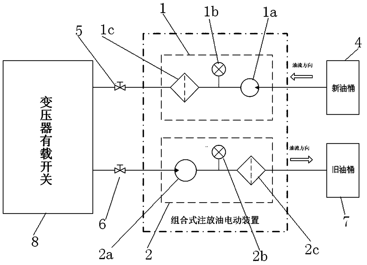
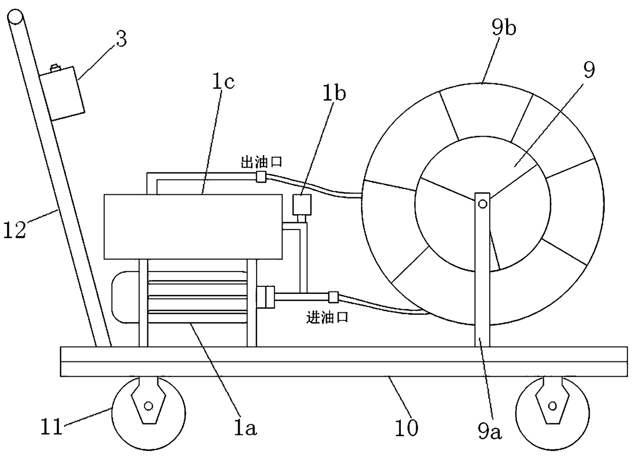
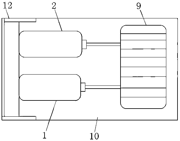
The invention discloses a combined oil injection and discharge electric device for replacing transformer oil. The oil injection and discharge electric device comprises a loading device and an oil injection and filter unit, an oil discharge and filter unit and a control box which are arranged on the loading device, wherein an oil inlet of the oil injection and filter unit communicates with a new oil drum through an oil pipe, and an oil outlet of the oil injection and filter unit communicates with an oil injection valve of a transformer through an oil pipe; an oil inlet of the oil discharge andfilter unit communicates with an oil discharge valve of the transformer, and an oil outlet of the oil discharge and filter unit communicates with an old oil drum through an oil pipe; a phase sequenceswitch is arranged in the control box and used to adjust a phase sequence to avoid repeated change of power supply wiring and reduce risk of low voltage electric shock. From the perspective of practical application, the combined oil injection and discharge electric device integrates the various working units to achieve high integration, and thus better satisfy actual work needs on site.

Description

technical field [0001] The invention relates to a multifunctional electric device for insulating oil treatment, in particular to a combined electric device for filling and discharging oil. Background technique [0002] The physical and chemical properties of transformer oil as the insulation and cooling medium of the transformer directly affect the overall insulation and heat dissipation performance of the transformer itself. During the switching process of the on-load tap changer, the transformer oil acts as an insulating medium and extinguishes the arc. After each tap changer switching, the transformer oil will produce decomposition products and free carbon, and the switching operation will also produce trace metal particles. These impurities deteriorate the oil quality, reduce the overall insulation level of the on-load tap-changer, limit the switching times and service life of the on-load tap-changer, and endanger the safe operation of the transformer. Aged insulating o...

Claims


Application Information

Patent Timeline
Patent Type & Authority Applications(China)
IPC IPC(8): B65H75/40B65H75/44H01F27/14C10G31/09
CPCH01F27/14C10G31/09B65H75/403B65H75/44B65H2701/33
Inventor 任龙朱增军张潇赵小迪
Owner JIANGSU ELECTRIC POWER CO
Learn More