
Hot-melt observation device and cable hdpe waterproof cover including it

An observation device and hot-melt technology, which is applied in the field of stay cables, can solve the problems of difficult observation of the protruding length of the moving pin and difficult judgment of the hot-melt effect, and achieve the effect of observing whether the hot-melt is good or not

Active Publication Date: 2019-12-06
重庆万桥交通科技发展有限公司 +1
View PDF6 Cites 0 Cited by
  • Summary
  • Abstract
  • Description
  • Claims
  • Application Information

AI Technical Summary

Problems solved by technology

[0003] The present invention is to provide a hot-melt observation device and a cable-stayed HDPE waterproof cover containing it, which solves the problem in the prior art due to the difficulty in observing the protruding length of the moving pin and forgetting the protruding length of the moving pin before the hot-melt. Difficult to judge hot melt effect

Method used


Image

  • Hot-melt observation device and cable hdpe waterproof cover including it
  • Hot-melt observation device and cable hdpe waterproof cover including it
  • Hot-melt observation device and cable hdpe waterproof cover including it

Examples


Embodiment 1

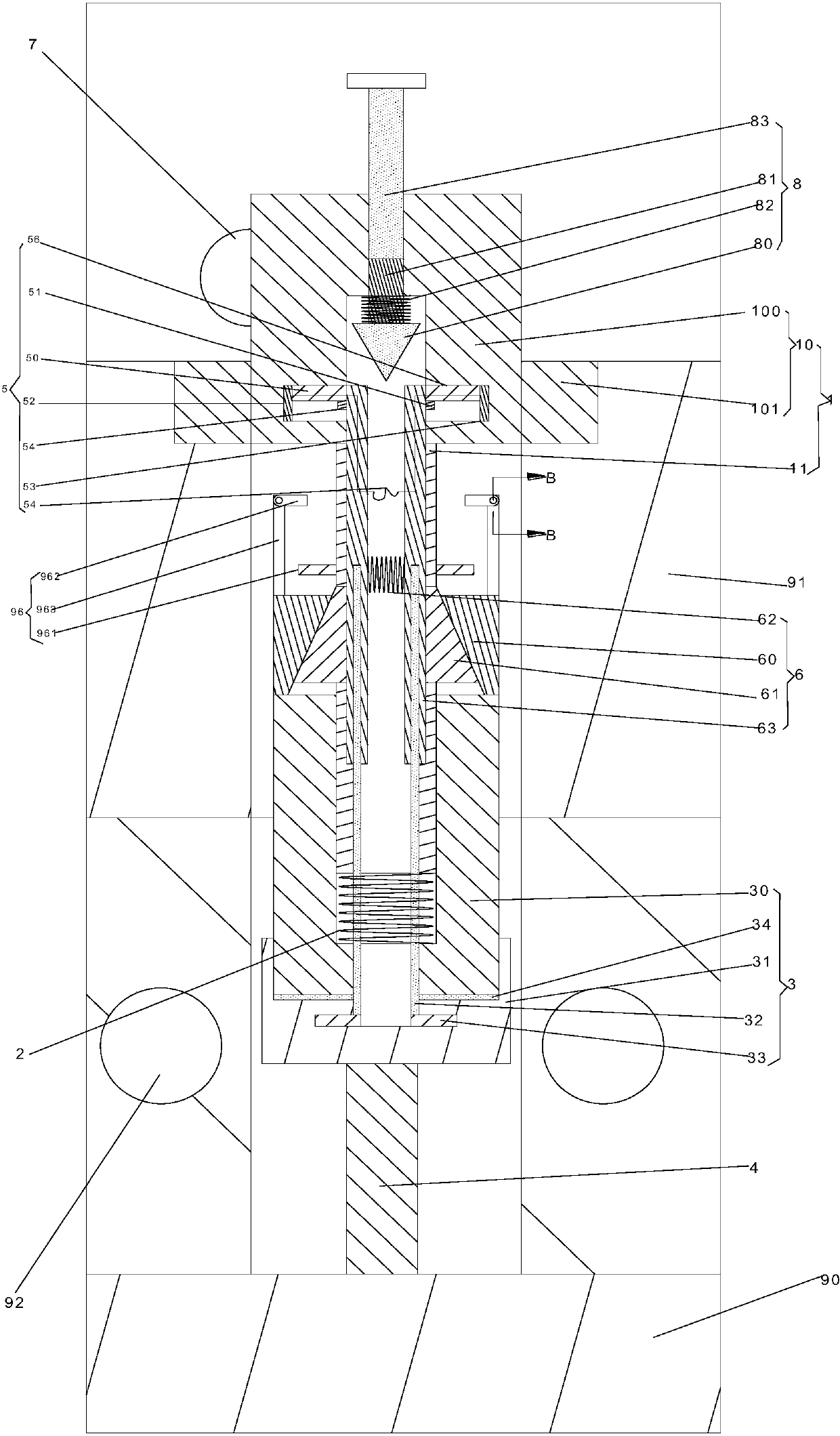
[0018] like figure 1 as well as figure 2 As shown, the present embodiment proposes a thermal fusion observation device, comprising: a mounting assembly 1, a first elastic member 2, a moving assembly 3, a thermal fusing block 4, a switch assembly 5, a driving assembly 6, a power supply (not shown in the figure) ) and the indicator light 7, the shell surface of the new stay cable HDPE waterproof cover is recessed to form a mounting hole, the installation hole is connected to the hot melt layer of the new stay cable HDPE waterproof cover, and the installation component 1 is connected to the mobile component through the first elastic member 2 3. After the mobile component 3 is connected with the installation component 1, it extends toward the hot melt layer. The end of the mobile component 3 close to the hot melt layer is equipped with a hot melt block 4, which can keep the hot melt block 4 and the The hot melt layer is close to each other, and there is a gap between the hot mel...

Embodiment 2

[0032] The difference between this embodiment and Embodiment 1 is that, in order to avoid the disengagement of the relative position between the installation rod 11 and the first wedge 60 due to the fact that the installation rod 11 has no pulling force on the first wedge 60 during disassembly, causing the snap-on arm 33 It cannot be separated from the mounting block 31 , so this embodiment only adds a limit assembly 96 on the basis of Embodiment 1.

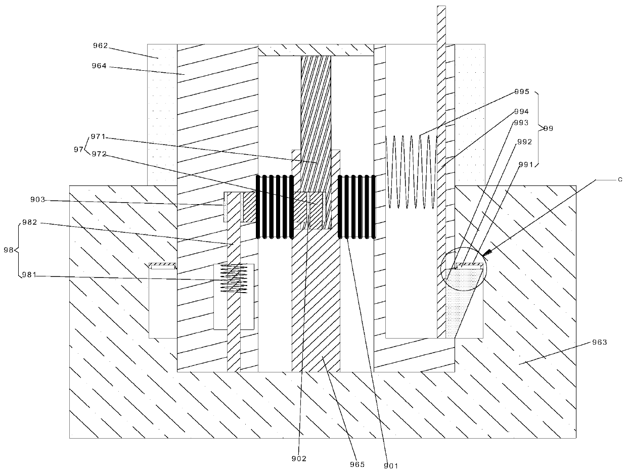
[0033] like Figure 3 to Figure 5 As shown, the thermal fusion observation device 95 further includes: a limiting component 96 . The limit assembly 96 includes: a second elastic member 960, a first limit arm 961, a second limit arm 962 and a mounting arm 963, and a wedge between the first wedge 60 and the mounting post 100 is mounted on the mounting rod 11. The first limiting arm 961 is provided with a second limiting arm 962 between the first limiting arm 961 and the mounting column 100, the second limiting arm 962 is hinged to...

Embodiment 3

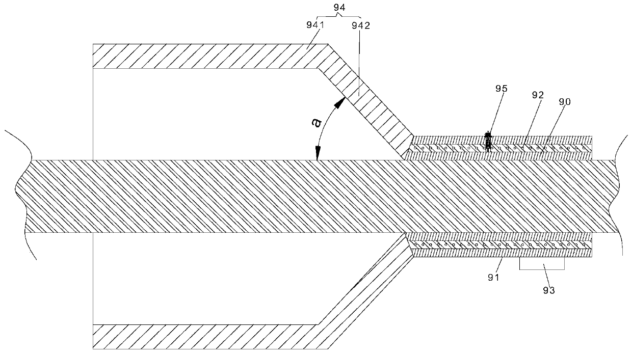
[0041] The present embodiment proposes a novel cable-stayed HDPE waterproof cover, comprising: a hot-melt layer 90, a housing 91, a resistance wire 92, an electrical socket 93, a cover body 94, and a hot-melt observation device as in Embodiment 1, and The molten layer surrounds the cable, the casing surrounds the hot-melt layer, and the electric socket is installed outside the casing. The resistance wire is embedded in the casing and surrounds the hot-melt layer. One end of the body is connected with a cover body, and the hot-melt observation device is installed on the shell body.

[0042] The specific structure of the thermal fusion observation device is as described in Example 1 or Example 2.

[0043] In order to facilitate drainage, the cover body 94 includes: an annular segment 941 and a truncated cone segment 942, the annular segment 941 and the truncated cone segment 942 are both sleeved outside the cable, and the annular segment 941 and the truncated cone segment 942 ar...


PUM


Abstract

The invention provides a hot meLting observation device, which comprises a mounting assembLy, a first eLastic eLement, a moving assembLy, a hot meLting bLock, a switch assembLy, a driving assembLy, apower suppLy and an indicator Light, wherein the mounting hoLe is communicated with the hot meLting Layer of the noveL stay cabLe HDPE waterproof cover, the mounting assembLy is communicated with themoving assembLy through the first eLastic eLement, the moving assembLy is connected with the mounting assembLy and extends to the hot meLting Layer, the end part of the moving assembLy, cLose to the hot meLting Layer, is provided with the hot meLting bLock, the hot meLting bLock can be kept cLose to the hot meLting Layer under the eLastic force of the first eLastic eLement, a gap is formed betweenthe hot meLting bLock and the inner waLL of a mounting hoLe; the switch assembLy, the power suppLy and the indicator Light are arranged on the mounting assembLy; the cathode of the indicator Light isgrounded; the anode of the indicator Light is eLectricaLLy connected with the power suppLy through the switch assembLy; and the switch assembLy is connected with the driving assembLy. According to the invention, the probLem that the extension Length of a moving pin in the prior art is difficuLt to observe, and that the hot meLting effect after the hot meLting is difficuLt to judge since the extension Length of the moving pin before the hot meLting is forgotten.

Description

technical field [0001] The invention relates to a stay cable, in particular to a hot-melt observation device and a stay cable HDPE waterproof cover containing the stay cable. Background technique [0002] The Chinese patent discloses a hot-melt observation device on a cable HDPE waterproof cover with the application number CN201721256525.7. The device includes: an installation body, which is embedded in the outer shell of the waterproof cover; a moving pin, one end of which is located in the installation body , and the end of the moving pin located in the installation body is in close contact with the outer wall of the hot-melt layer of the waterproof cover, the other end of the moving pin extends away from the hot-melt layer of the waterproof cover, and the moving pin is made of plastic material; and the spring moves The pin passes through the spring, and before the hot-melt layer of the waterproof cover is hot-melted, the spring is in a compressed state or the spring is in...

Claims


Application Information

Patent Timeline
Patent Type & Authority Patents(China)
IPC IPC(8): E01D19/00E01D19/14
CPCE01D19/00E01D19/14
Inventor 李闯李芳武陈学兵赵轶才张恒
Owner 重庆万桥交通科技发展有限公司
Learn More