Environment-friendly energy-saving multifunctional wind barrier

An energy-saving and multi-functional technology, applied in the wind resistance of railway bridges and roads, can solve the problems of ineffective use of clean energy, poor wind resistance of wind noise barriers, and poor safety performance, so as to reduce secondary damage and improve wind resistance Capability, little effect on mechanical wear

Pending Publication Date: 2018-11-23
CENT SOUTH UNIV +1
View PDF0 Cites 6 Cited by
  • Summary
  • Abstract
  • Description
  • Claims
  • Application Information

AI Technical Summary

Problems solved by technology

[0005] The purpose of the present invention is to provide an environmentally friendly and energy-saving multifunctional wind-acoustic barrier to solve the problems of poor wind resistance, poor safety performance and ineffective use of clean energy in the prior art.

Method used


Image

  • Environment-friendly energy-saving multifunctional wind barrier
  • Environment-friendly energy-saving multifunctional wind barrier
  • Environment-friendly energy-saving multifunctional wind barrier

Examples


Embodiment 1

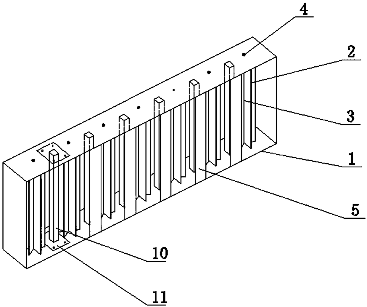
[0037] see figure 1 , figure 2 , Figure 4 , Figure 5 , Image 6 , Figure 7 , an environment-friendly and energy-saving multifunctional wind-sound barrier, which is applied to vehicle bridges 8 and vehicle roads 9 in this embodiment.

[0038] An environment-friendly and energy-saving multifunctional wind noise barrier, comprising a supporting frame 1, a rotating impeller 2, and a rotating shaft 3; the supporting frame 1 is a hollow cuboid structure, and the two opposite sides where the length and height are located are open, and the other four sides are open. Closed; the rotating impeller 2 is a cylindrical structure, and the rotating shaft 3 passes through the rotation center of the rotating impeller and is connected by a flat key; the rotating impeller 2 is provided with at least two groups.

[0039] The two ends of the rotating shaft 3 are respectively connected with the upper surface and the lower bottom surface of the supporting frame through the magnetic suspensi...

Embodiment 2

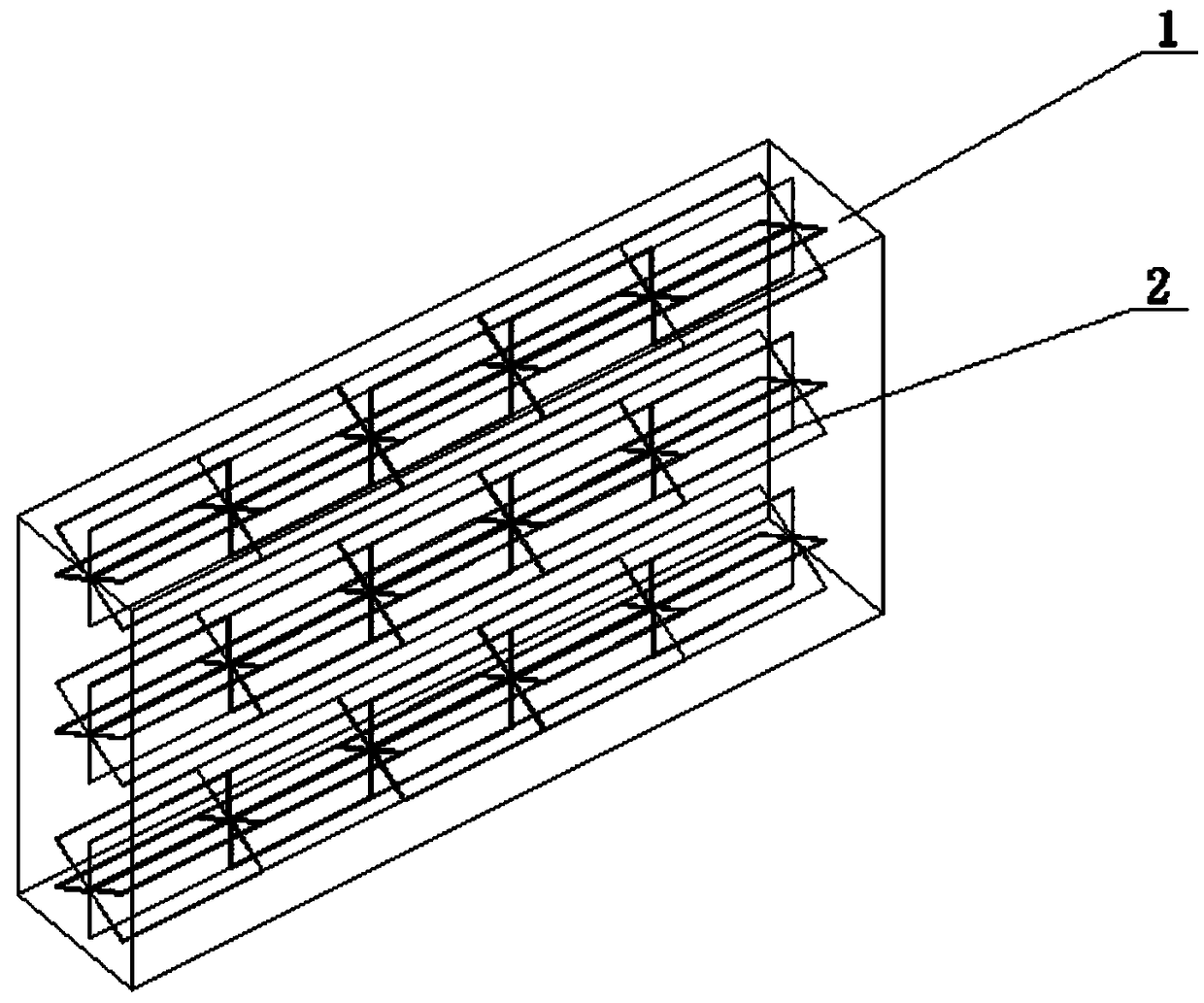
[0055] see figure 1 , image 3 , Figure 4 , Figure 5 , Image 6 , Figure 7 , The difference between this embodiment and Embodiment 1 is that: the rotating shaft 3 is installed parallel to the upper and lower surfaces of the support frame 1, that is, the rotating impeller is arranged in a horizontal direction.

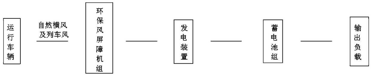
[0056] The working principle of this embodiment is specifically: the natural cross wind or the wind generated by the vehicle during driving is rectified by the deflector 6, so that the wind is smoothly transmitted to the wind-sound barrier 7, and the wind drives the rotating impeller 2 to rotate, and generates electricity The device converts wind energy into electrical energy and stores the electrical energy in the storage device; at the same time, in fine weather, the solar photovoltaic panels can also convert solar energy into electrical energy and store the electrical energy in the storage device. When electricity is needed, an external output load, such as a...


PUM


Abstract

The invention provides an environment-friendly energy-saving multifunctional wind barrier which comprises a hollow rectangular supporting frame, a cylindrical rotating impeller and a rotating shaft. Two opposite surface of the length and the height are opened, the other four surfaces are closed, the rotating shaft penetrates the rotating center of the rotating impeller and is connected with the rotating impeller through a flat key, the rotating shaft is connected with the supporting frame through a magnetic suspension bearing, the rotating impeller is mounted in the supporting frame along thelength direction in a backlash uniformity manner and connected with a power generation device, the power generation device is connected with a storage battery, and the storage battery is connected with an output load. The barrier is provided with a wind power generation device and a solar power generation device, solar energy and wind energy can be sufficiently utilized, energy is saved, environments are protected, wind power can be effectively resisted by the cylindrical rotating impeller, a transverse wind load directly acting on the surface of a train is reduced and steered, air flow perpendicular to the wind barrier is guided and consumed, safety of road traffic and the wind barrier is ensured, magnetic bearing is selected, low in noise and smooth in rotation, and the service life of the wind barrier is remarkably prolonged.

Description

technical field [0001] The invention relates to the technical field of wind resistance of highways and railway bridges, in particular to an environment-friendly and energy-saving multifunctional wind-sound barrier. Background technique [0002] In recent years, with the rapid development of my country's economy, transportation construction has also made remarkable achievements. The construction of public transportation, especially expressways and high-speed railways, has developed rapidly from scratch. Especially in the construction of high-speed railways in the past ten years, in order to ensure the high-speed and stable operation of trains, the way of replacing roads with bridges has become increasingly prominent. , the strong wind poses a safety threat to vehicle operation. Therefore, solving such problems has become an urgent key difficulty. [0003] At present, in the conventional operation control mode, the wind and sound barriers are built on both sides of the road ...

Claims


Application Information

Patent Timeline
Patent Type & Authority Applications(China)
IPC IPC(8): E01F7/02E01F8/00H02S20/21
CPCE01F7/025E01F8/00E01F8/0023H02S20/21Y02E10/50
Inventor 何旭辉邹思敏
Owner CENT SOUTH UNIV
Why Eureka
Try Eureka