Wall building robot

A technology of wall-building robots and mechanical claws, applied in manipulators, manufacturing tools, construction, etc., can solve the problems of large bricks, large quantities, and time-consuming

Active Publication Date: 2018-11-23
NANTONG UNIVERSITY
View PDF5 Cites 15 Cited by
  • Summary
  • Abstract
  • Description
  • Claims
  • Application Information

AI Technical Summary

Problems solved by technology

[0003] Aiming at the deficiencies of the prior art, the present invention provides a wall-building robot, which has the advantages of saving a lot of manpower and material resources without manual work, and solves the probl

Method used


Image

  • Wall building robot
  • Wall building robot
  • Wall building robot

Examples


Embodiment 1

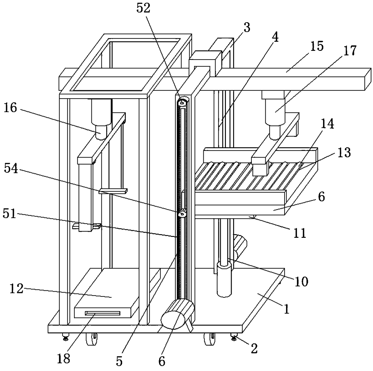
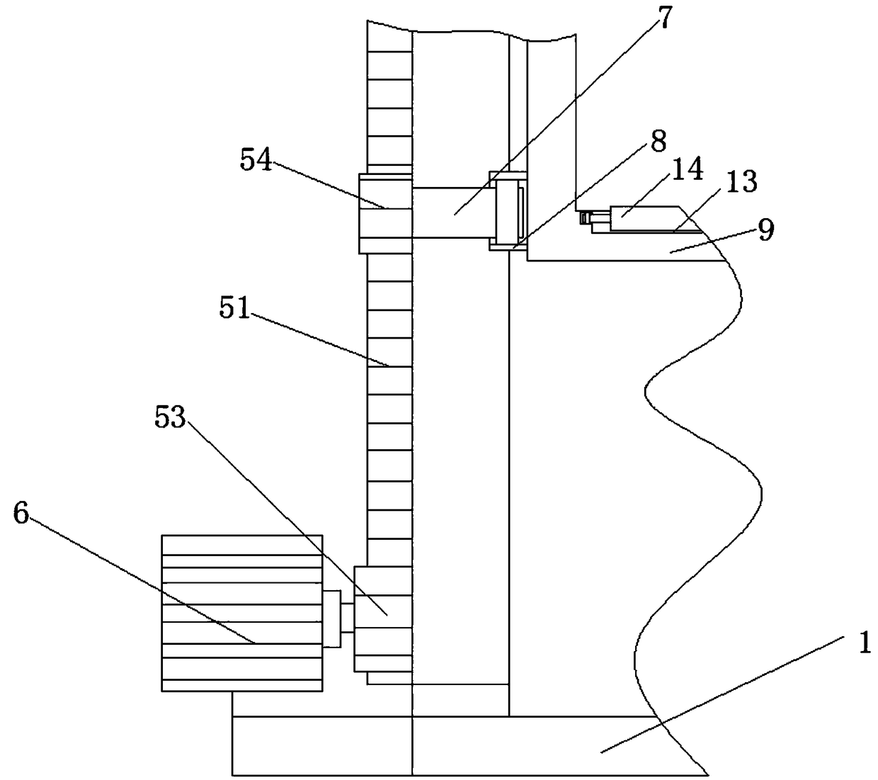
[0022] see Figure 1-2 , the present embodiment provides a wall-building robot, comprising a bottom plate 1, the top of the bottom plate 1 is fixedly connected with a fixed frame 3, and both sides of the inner wall of the fixed frame 3 are provided with moving ports 4, and both sides of the fixed frame 3 are provided with There is a transmission assembly 5, one side of the transmission assembly 5 is provided with a motor 6, the inner wall of the moving port 4 is slidingly connected with a rotating shaft 7, one side of the rotating shaft 7 is rotatingly connected with a rotating seat 8, and one side of the rotating seat 8 is fixedly connected with a brick Platform 9, the top of base plate 1 is fixedly equipped with cylinder 10, and the top of cylinder 10 is fixedly connected with support plate 11, and support plate 11 is movably connected with brick setting platform 9. The top of base plate 1 is movably connected with brick plate 12, fixed frame 3 Inner wall top is fixedly conn...

Embodiment 2

[0025] see Figure 1-2 , made further improvement on the basis of Embodiment 1: the transmission assembly 5 includes a gear belt 51, an upper positioning gear 52 and a lower positioning gear 53, the lower positioning gear 53 is fixedly connected with the output shaft of the motor 6, and the inner wall of the gear belt 51 The connecting gear 54 is meshed, and the connecting gear 54 is fixedly connected with the rotating shaft 7. When carrying out the lifting of the brick table 9, the positioning gear 53 is driven by the motor 6 to rotate, so that the gear belt 51 is rotated, and the gear belt 51 drives the connecting gear 54 to rotate. The internal movement of the gear belt 51 enables the rotating shaft 7 to move in the vertical direction, wherein the moving port 4 can well limit the rotating shaft 7 to prevent it from shifting.

[0026] Wherein, the bottom of the bottom plate 1 is movably connected with a moving wheel, and the bottom of the bottom plate 1 is fixedly connected ...

Embodiment 3

[0028] see Figure 1-2 , on the basis of Embodiment 1, a further improvement has been made: the inner wall of the rotating seat 8 is provided with a bearing, and the rotating shaft 7 is socketed with the inner edge of the bearing, so that the rotating shaft 7 can rotate more smoothly, so that the connecting gear 54 can rotate more smoothly , the top of the brick platform 9 is provided with a mounting groove 13, the inner wall of the mounting groove 13 is rotatably connected with a running wheel 14, and the surface of the rotating wheel 14 is provided with a rubber sleeve, by setting the rotating wheel 14, it is convenient for the follow-up brick plate 12 The used brick plate 12 is extruded from the brick platform 9 to prevent material accumulation on the brick platform 9.

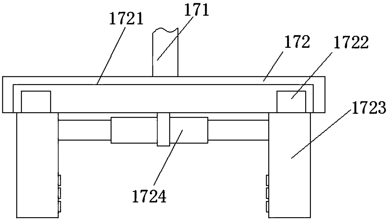
[0029] Wherein, the upper brick mechanical claw 16 includes a driving cylinder and a brick claw, and the inner wall of the brick claw is provided with a block, and both sides of the brick plate 12 are provi...


PUM


Abstract

The invention relates to the technical field of building machinery, and discloses a wall building robot. The wall building robot comprises a bottom plate, wherein the top of the bottom plate is fixedly connected with an installation fixing frame; a moving opening is formed in each of the two sides of the inner wall of the fixing frame; a transmission assembly is arranged at each of the two sides of the fixing frame; a motor is arranged at one side of the transmission assembly; the inner wall of the moving opening is glidingly connected with a rotating shaft; one side of the rotating shaft is rotationally connected with a rotating seat; one side of the rotating seat is fixedly connected with a brick placing table; the top of the bottom plate is fixedly provided with an air cylinder; the topof the air cylinder is fixedly connected with a support plate; the support plate and the brick placing table are movably connected; the top of the bottom plate is movably connected with a brick placing plate; the top of the inner wall of the fixing frame is fixedly connected with slide rails. The wall building robot solves the problems that the existing wall building mode is most labor operation;the engineering quantity is great, and the brick mass is great, so that a large amount of labor and materials are needed for wall building; much time is consumed.

Description

technical field [0001] The invention relates to the technical field of construction machinery, in particular to a wall-laying robot. Background technique [0002] When building walls, most owners still choose conventional masonry construction methods as before. The walls of houses built in this way can play a role in air temperature buffering, thereby ensuring moderate indoor temperature and humidity. Most of them are operated by manpower. Due to the large amount of work and the high quality of the bricks, a large amount of manpower and material resources are needed to build walls, and it takes more time. Contents of the invention [0003] Aiming at the deficiencies of the prior art, the present invention provides a wall-building robot, which has the advantages of saving a lot of manpower and material resources without the need for manual wall-building, and solves the problem that the existing wall-building methods are mostly operated by manpower. Larger, and the quality ...

Claims


Application Information

Patent Timeline
IPC IPC(8): E04G21/22B25J5/00B25J11/00
CPCB25J5/007B25J11/00E04G21/22
Inventor 徐向红
Owner NANTONG UNIVERSITY
Why Eureka
Try Eureka