Cartridge valve for lifting equipment

A technology of lifting equipment and cartridge valves, applied in mechanical equipment, fluid pressure actuators, servo motor components, etc., can solve the problems of high cost, complex oil circuit, and bulky valve block, and achieve simple structure and compact volume , cost reduction effect

Inactive Publication Date: 2018-11-23
佛山信卓派思机械科技有限公司
View PDF0 Cites 2 Cited by
  • Summary
  • Abstract
  • Description
  • Claims
  • Application Information

AI Technical Summary

Problems solved by technology

Most of the upgraded equipment adopts the hydraulic system to control the rise, fall and stop pressure of the hydraulic cylinder. The existing technology generally adopts the integration of electromagnetic reversing valves, balance valves, throttle valves, hydraulic locks, etc. on the valve block, resulting in complex oil circuits and The valve block is bulky, heavy and expensive

Method used


Image

  • Cartridge valve for lifting equipment
  • Cartridge valve for lifting equipment
  • Cartridge valve for lifting equipment

Examples


Embodiment Construction

[0017] The present invention will be further described in detail below in conjunction with the accompanying drawings and embodiments.

[0018] Such as Figure 1~3 Shown is a preferred embodiment of the present invention.

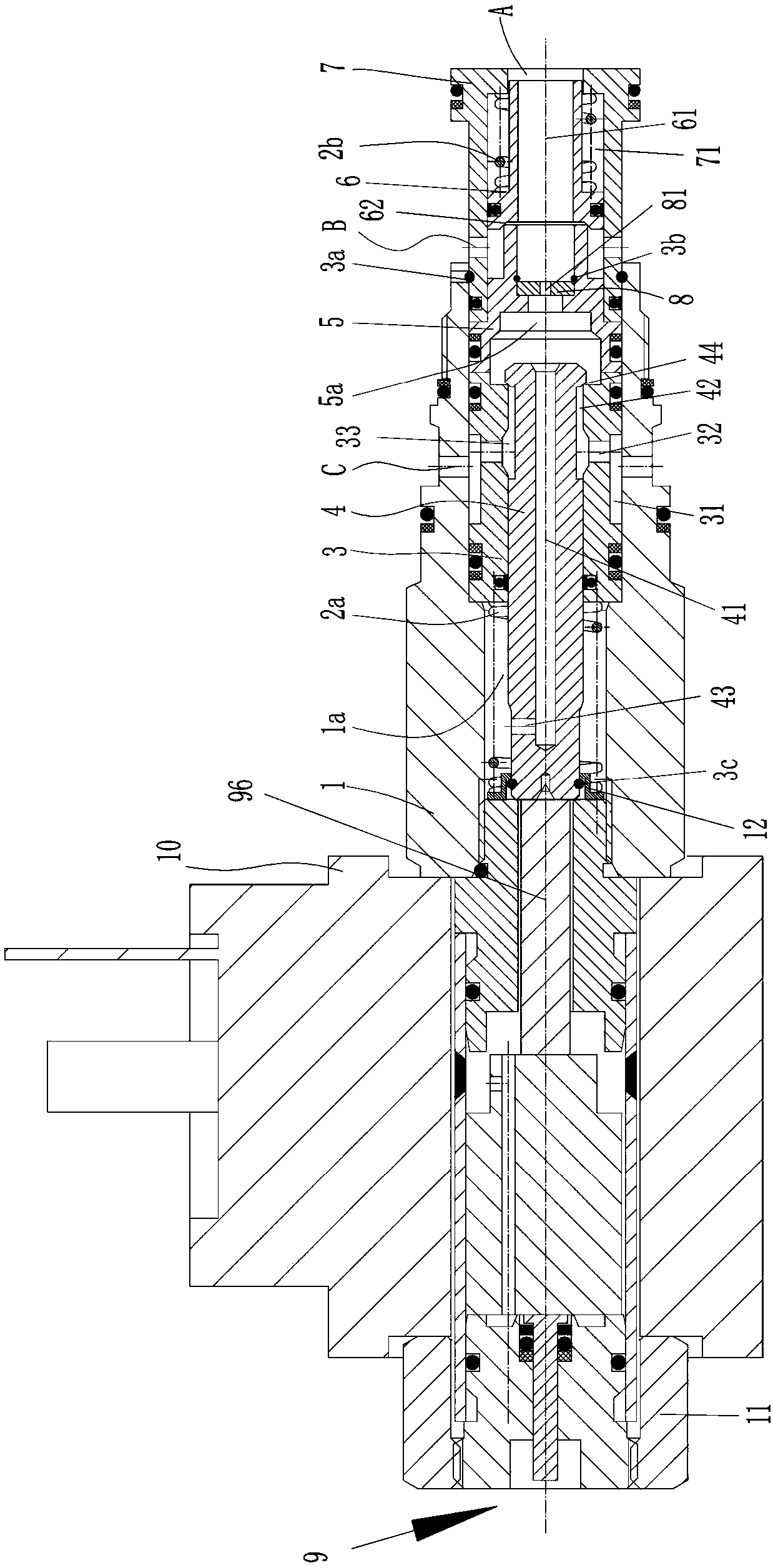
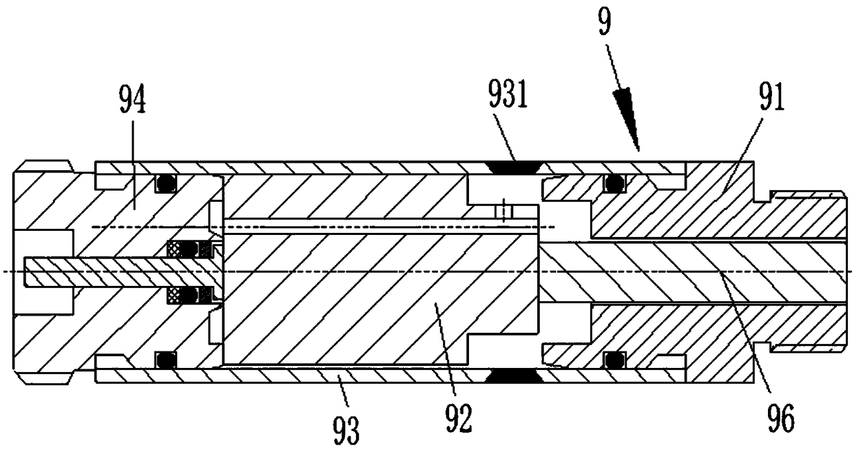
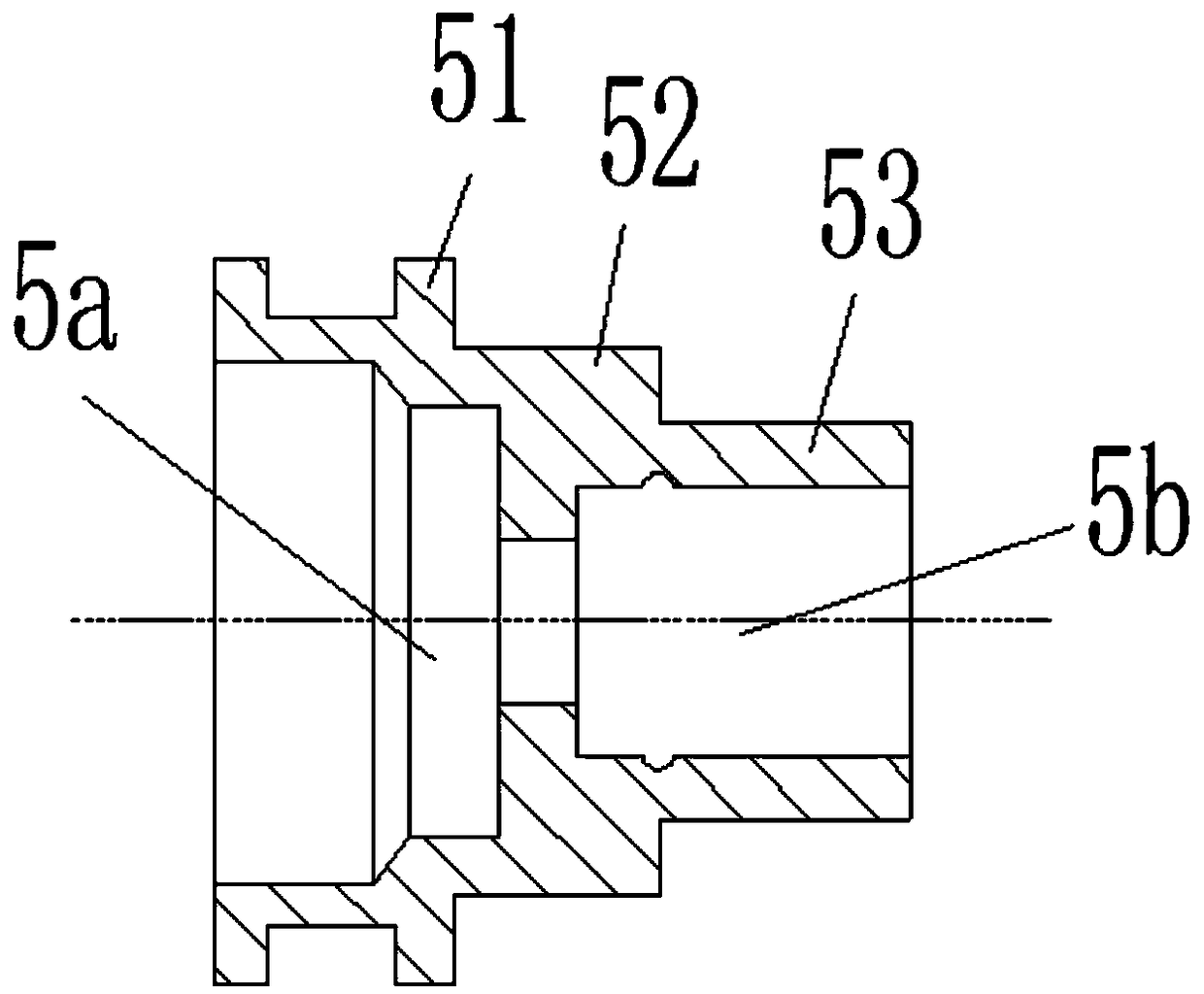
[0019] A cartridge valve for lifting equipment, including a magnetic sleeve assembly 9, a push rod 96, a coil 10, a nut 11, a valve body 1, a first valve sleeve 3, a cone valve core 4, a spring seat 12, and a first spring 2a, valve seat 5, throttle plate 8, second valve sleeve 7, one-way valve core 6 and second spring 2b.

[0020] The magnetic sleeve assembly 9 comprises a static iron 91, an armature 92, a magnetic tube 93, and a plug 94. The magnetic tube 93 is hollow to form an inner cavity, and the left end of the static iron 91 stretches into the inner cavity of the magnetic tube 93 and is pressed and The magnetic tube 93 forms a fixed connection, the armature 92 slides in the inner cavity of the magnetic tube 93, the right end of the plug 94 extends i...


PUM


Abstract

The invention relates to a cartridge valve for lifting equipment. The cartridge valve for lifting equipment is characterized by comprising a magnetic conductive sleeve assembly, a push rod, a coil, avalve body, a first valve sleeve, a cone valve element, a spring seat, a first spring, a valve seat, a throttling sheet, a second valve sleeve, a one-way valve element and a second spring. A third oilport is formed in the valve body, and a first oil port and a second oil port are formed in the second valve seat; the cone valve element is matched with a valve hole in the first valve sleeve to control on and off of the first oil port and the second oil port; the one-way valve element is matched with the valve seat to control on and off of the first oil port and the second oil port. The cartridge valve of an inserted design is compact in structure and low in processing cost, and can be used for ascending and descending pressure lifting equipment and stopping pressurizing control.

Description

technical field [0001] The invention belongs to the technical field of valves, in particular to a cartridge valve used for lifting equipment. Background technique [0002] Lifting equipment is a widely used equipment, which mainly includes lifts, climbing work platforms, lifting platforms for the disabled, car repair lifts, etc. Most of the upgraded equipment adopts the hydraulic system to control the rise, fall and stop pressure of the hydraulic cylinder. The existing technology generally adopts the integration of electromagnetic reversing valves, balance valves, throttle valves, hydraulic locks, etc. on the valve block, resulting in complex oil circuits and The valve block is bulky, heavy and expensive. Contents of the invention [0003] The technical problem to be solved by the present invention is to provide a cartridge valve with simple structure, low manufacturing cost, simplification of the oil circuit of the valve block, and completion of the ascending, descending...

Claims


Application Information

Patent Timeline
Patent Type & Authority Applications(China)
IPC IPC(8): F15B13/01F15B13/02
CPCF15B13/01F15B13/02F15B13/027F15B2013/004
Inventor 不公告发明人
Owner 佛山信卓派思机械科技有限公司
Why Eureka
Try Eureka