Valve rod valve rotating device

A technology of rotating devices and valves, which is applied in the direction of valve devices, valve operation/release devices, valve details, etc., can solve the problems of increasing production costs of enterprises and increasing capital investment of rotating equipment, so as to reduce production costs of enterprises and improve compatibility of use sexual effect

Pending Publication Date: 2018-11-23
江苏容大材料腐蚀检验有限公司
View PDF5 Cites 0 Cited by
  • Summary
  • Abstract
  • Description
  • Claims
  • Application Information

AI Technical Summary

Problems solved by technology

However, corresponding to different specifications of stem valves, it is necessary to configure corresponding rotating equipment with different structures; Structured rotating equipment, in this way, will increase the capital investment of rotating equipment and increase the production cost of enterprises

Method used


Image

  • Valve rod valve rotating device
  • Valve rod valve rotating device
  • Valve rod valve rotating device

Examples


Embodiment 1

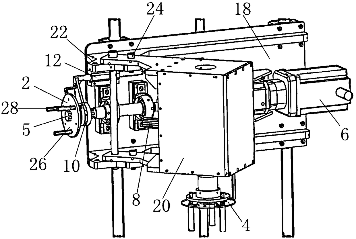
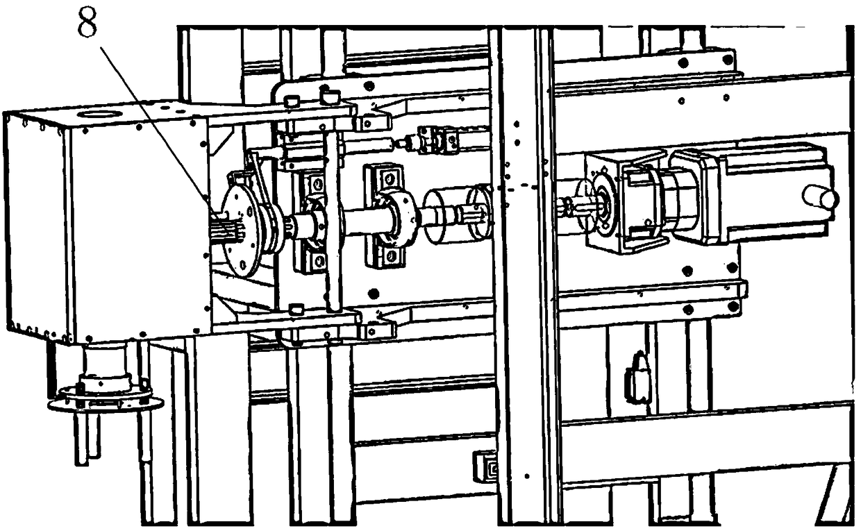
[0019] like Figure 1-2 As shown, this embodiment discloses a valve stem valve rotation device, including a first rotary actuator 2 and a second rotary actuator 4, the first rotary actuator 2 is fixed on the first spline shaft 5, and the first rotary actuator 4 is fixed on the first spline shaft 5. A spline shaft 5 rotates horizontally under the drive of the power source; the above-mentioned second rotary actuator 4 is fixed on the transmission mechanism, and the above-mentioned transmission mechanism can convert the horizontal rotation into vertical rotation; the above-mentioned transmission mechanism is fixed on the second spline shaft 8 Above; the above-mentioned first spline shaft 5 is spline-coupled with a sliding sleeve 10; the above-mentioned sliding sleeve 10 is connected to the switching mechanism, and the above-mentioned switching mechanism drives the sliding sleeve 10 to move axially along the first spline shaft 5, so that the second spline The key shaft 8 is spline...

Embodiment 2

[0029] This embodiment discloses a valve stem valve rotation device. The difference between this embodiment and Embodiment 1 lies in the structure of the transmission mechanism. In the technical solution of this embodiment, the above-mentioned transmission mechanism is a first bevel gear and a second For the bevel gear, the above-mentioned first bevel gear is spline-coupled to the second spline shaft, and the above-mentioned second rotary actuator is fixed on the wheel shaft of the second bevel gear. The above-mentioned first bevel gear rotates horizontally, which drives the second bevel gear to rotate vertically. The transmission mechanism with the above structure can also realize the transformation of horizontal rotation and vertical rotation.


PUM


Abstract

The invention discloses a valve rod valve rotating device. The valve rod valve rotating device comprises a first rotation actuator and a second rotation actuator, wherein the first rotation actuator is fixed to a first spline shaft; the first spline shaft is driven to rotate horizontally by a power source; the second rotation actuator is fixed to a transmission mechanism; the transmission mechanism can transform horizontal rotation into vertical rotation; the transmission mechanism is fixed to the second spline shaft; the first spline shaft is in splined coupling with a sliding sleeve; the sliding sleeve is connected to a switching mechanism; the switching mechanism is used for driving the sliding sleeve to move along the axial direction of the first spline shaft, so that the second splineshaft is in splined coupling in the sliding sleeve, or separated from the sliding sleeve. The valve rod valve rotating device is driven by the power source, so that opening or closing of a horizontalwheel valve and a vertical wheel valve is realized, the usage compatibility of rotation equipment is improved, and the production cost of enterprises is lowered.

Description

technical field [0001] The invention relates to a rotary actuator, in particular to a rotary device for automatically opening or closing a stem valve. Background technique [0002] In recent years, with the rapid development of the global petrochemical industry, the organic emission compounds (VOCs) of petrochemical plants are on the rise year by year. According to statistics, 60% of the VOCs in the petrochemical industry are produced by valve leakage, and the leakage at the packing is the main leakage. aisle. In order to effectively control the leakage of the valve, the leakage measurement (ie fugitive measurement) is introduced into the valve measurement standard. The fugitive measurement of the valve requires simultaneous measurement of the leakage when the valve is open and closed. The opening or closing of the valve stem is finally converted into turning the handwheel connected to the valve stem. At present, there are two ways to open or close the stem valve, one is t...

Claims


Application Information

Patent Timeline
Patent Type & Authority Applications(China)
IPC IPC(8): F16K31/122F16K31/60F16K31/53
CPCF16K31/12F16K31/53F16K31/60
Inventor 李瑞王雷李剑
Owner 江苏容大材料腐蚀检验有限公司
Why Eureka
Try Eureka