Overload prevention combined type variable spring supporter and hanger utilizing threaded rod to lock

An anti-overload, combined technology, applied in the direction of springs, pipe supports, springs/shock absorbers, etc., can solve the problems of complicated installation operations, the inability to adjust the position of variable spring supports and hangers according to site conditions, and low safety performance. Achieve the effect of improving safety, facilitating maintenance operations, and improving service life

Pending Publication Date: 2018-11-23
JIANGSU DALICHENG ELECTRICAL
View PDF0 Cites 2 Cited by
  • Summary
  • Abstract
  • Description
  • Claims
  • Application Information

AI Technical Summary

Problems solved by technology

[0004] The purpose of the present invention is to solve the problems that the existing variable spring support and hanger cannot adjust the position according to the site conditions, the installation operation is complicated, and the safety performance is low, and a kind of anti-overload combined variable spring support and hanger using screw locking is proposed

Method used


Image

  • Overload prevention combined type variable spring supporter and hanger utilizing threaded rod to lock
  • Overload prevention combined type variable spring supporter and hanger utilizing threaded rod to lock
  • Overload prevention combined type variable spring supporter and hanger utilizing threaded rod to lock

Examples


Embodiment 1

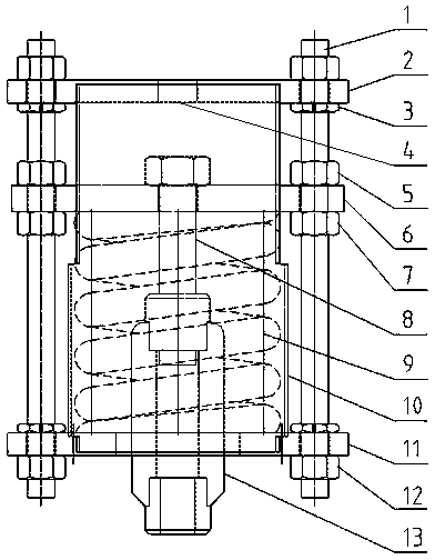
[0024] Such as figure 2 As shown, an anti-overload combined variable spring hanger that adopts screw locking, its structure includes an upper cover plate, a spring pressing plate, a spring, a spring housing, and a lower cover plate; wherein the spring pressing plate is arranged on the upper cover plate and the lower cover Between the plates, a spring is installed between the lower surface of the spring pressure plate and the upper surface of the lower cover, and the spring housing is arranged outside the spring, and its upper and lower ends are respectively connected and fixed with the upper cover and the lower cover; two locks Bolts respectively pass through the holes on the left and right sides of the upper cover plate, the bayonet sockets on the left and right sides of the spring pressure plate, and the holes on the left and right sides of the lower cover plate.

[0025] The upper cover is respectively connected with two locking bolts through two flat nuts, and a tie rod n...

Embodiment 2

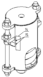
[0028] Such as image 3 As shown, an anti-overload combined variable spring hanger that adopts screw locking, its structure includes an upper cover plate, a spring pressing plate, a spring, a spring housing, and a lower cover plate; wherein the spring pressing plate is arranged on the upper cover plate and the lower cover Between the plates, a spring is installed between the lower surface of the spring pressure plate and the upper surface of the lower cover, and the spring housing is arranged outside the spring, and its upper and lower ends are respectively connected and fixed with the upper cover and the lower cover; two locks Bolts respectively pass through the holes on the left and right sides of the upper cover plate, the bayonet sockets on the left and right sides of the spring pressure plate, and the holes on the left and right sides of the lower cover plate.

[0029] The upper cover plate is respectively connected with two locking bolts through two flat nuts, a single h...

Embodiment 3

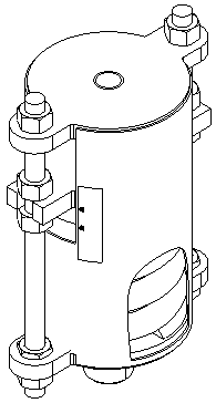
[0032] Such as Figure 4 As shown, an anti-overload combined variable spring hanger that adopts screw locking, its structure includes an upper cover plate, a spring pressing plate, a spring, a spring housing, and a lower cover plate; wherein the spring pressing plate is arranged on the upper cover plate and the lower cover Between the plates, a spring is installed between the lower surface of the spring pressure plate and the upper surface of the lower cover, and the spring housing is arranged outside the spring, and its upper and lower ends are respectively connected and fixed with the upper cover and the lower cover; two locks Bolts respectively pass through the holes on the left and right sides of the upper cover plate, the bayonet sockets on the left and right sides of the spring pressure plate, and the holes on the left and right sides of the lower cover plate.

[0033] The upper cover plate is respectively connected with two locking bolts through two flat nuts. There is ...


PUM


Abstract

The invention provides an overload prevention combined type variable spring supporter and hanger utilizing a threaded rod to lock. The overload prevention combined type variable spring supporter and hanger structurally comprises an upper cover plate, a spring pressure plate, a spring, a spring housing and a lower cover plate, wherein the spring pressure plate is arranged between the upper cover plate and the lower cover plate; the spring is mounted between the lower surface of the spring pressure plate and the upper surface of the lower cover plate; the spring housing is arranged outside the spring; the upper end of the spring housing is connected with and fixed to the upper cover plate; the lower end of the spring housing is connected with and fixed to the lower cover plate; one of two locking bolts penetrate through a hole in the left side of the upper cover plate, a bayonet in the left side of the spring pressure plate, and a hole in the left side of the lower cover plate; and the other locking bolt penetrates through a hole in the right side of the upper cover plate, a bayonet in the right side of the spring pressure plate, and a hole in the right side of the lower cover plate.The overload prevention combined type variable spring supporter has the advantages that (1) precise locking can be realized according to a measured value, and error influence is avoided; (2) a setting value can be modified, no replacement is required, and the cost is reduced; (3) locking again can be realized during overhaul and the operation is facilitated; and (4) with the adoption of a combined structure, the service life of a product is prolonged.

Description

technical field [0001] The invention relates to an anti-overload combined variable spring support hanger adopting screw locking, which belongs to the technical field of pipeline and equipment support. Background technique [0002] The variable spring support and hanger is mainly used for the support of thermal pipelines and equipment that require vertical displacement. It can adapt to the requirements of changes in the displacement of pipelines and equipment, and provide support and protection for pipelines and equipment. The traditional variable spring support and hanger is locked by a pin, and the locked position is determined by theoretical calculation, but due to the manufacturing error of the spring, the spring cannot be locked precisely at the design position, and once locked, its position cannot be changed; due to field equipment parameters The adjustment often needs to change the setting value of the spring support and hanger. At this time, it can only be remanufactu...

Claims


Application Information

Patent Timeline
IPC IPC(8): F16L3/205F16F15/04
CPCF16F15/04F16L3/2056F16F2230/0005F16F2230/0047F16F2238/026
Inventor 高勇孙庆勇
Owner JIANGSU DALICHENG ELECTRICAL
Why Eureka
Try Eureka