
Device and method for measuring response time and speed of proportional electromagnet action

A technology of proportional electromagnet and action response, applied in the direction of magnetic performance measurement, etc., can solve the problems of increased measurement complexity, broken armature push rod, and difficult measurement, so as to achieve accurate and reliable induction signals, not easy to be damaged by impact, and improve The effect of temporal resolution

Active Publication Date: 2020-03-24
NANJING UNIV
View PDF8 Cites 0 Cited by
  • Summary
  • Abstract
  • Description
  • Claims
  • Application Information

AI Technical Summary

Problems solved by technology

Another feature of the dynamic response of the electromagnet - "action time response", that is, the time it takes from the electromagnet to the armature to move to the maximum position (the limit piece, the limit piece is generally fixed on the shell), because it is difficult to predict in advance To master the actual moving distance of the electromagnet armature of different individuals, the general position sensor is often damaged by the armature push rod, or there is a large measurement error and the complexity of the measurement is increased, resulting in low measurement accuracy and difficult measurement. At present, almost no Do the "action time response" measurement

Method used


Image

  • Device and method for measuring response time and speed of proportional electromagnet action
  • Device and method for measuring response time and speed of proportional electromagnet action

Examples


Embodiment 1

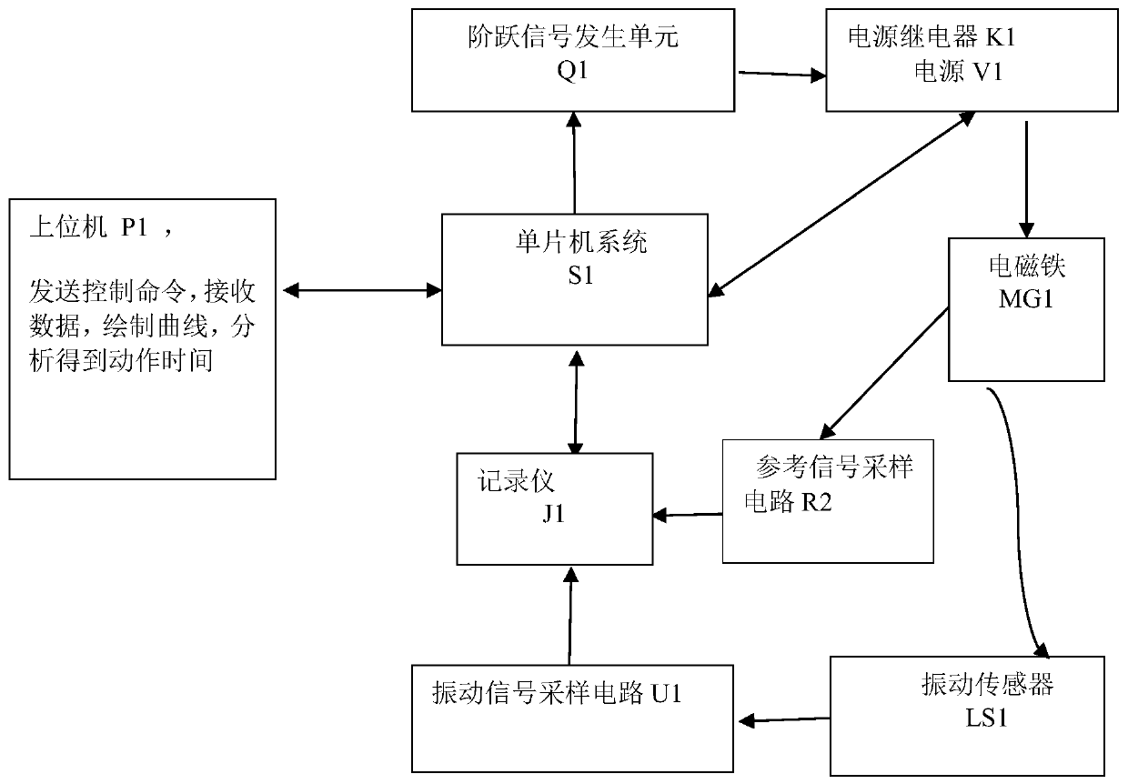
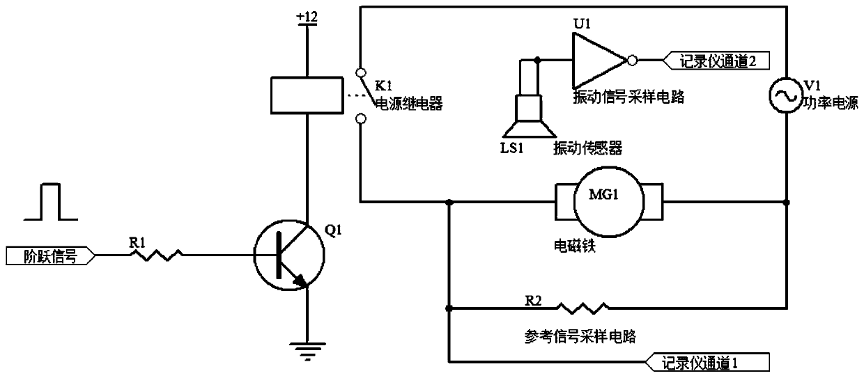
[0018] The device for measuring the action response time and speed of the proportional electromagnet includes: power relay K1, step signal generating unit Q1, reference signal sampling circuit R2, vibration sensor LS1, vibration signal sampling circuit U1, recorder J1, single-chip microcomputer system S1, The host computer P1, the step signal generating unit Q1 generates a step pulse signal and loads it on the power relay K1; the power relay K1 is used to control the on / off of the electromagnet power supply V1; the reference signal sampling circuit R2 It is connected in parallel with the coil of the electromagnet MG1, and is used to collect the electric pulse signal that excites the action of the armature of the electromagnet MG1; the vibration sensor LS1 is attached to the shell of the electromagnet MG1, and the vibration signal sampling circuit U1 is used to collect the signal of the vibration sensor LS1 The vibration signal is received, and the vibration signal comes from th...

Embodiment 2

[0020] The method for measuring the action response time and speed of the proportional electromagnet is realized based on the device of embodiment 1, and its steps include:

[0021] (1) The single-chip microcomputer generates a step pulse signal and loads it on the power relay; the pulse width is 10 milliseconds to 5000 milliseconds, the pulse width is 0 to 5V, and the rise / fall time of the step signal is less than 1 microsecond.

[0022] (2) The power supply relay is connected to the power supply to control the connection of the electromagnet power supply, thereby stimulating the movement of the electromagnet armature; the power supply is controlled by the single-chip microcomputer, and the output power is adjustable.

[0023] (3) The reference signal sampling circuit collects the voltage signal that excites the movement of the electromagnet armature and transmits it to the first channel of the recorder; through the sampling circuit, the voltage data obtained by the electromag...


PUM


Abstract

The invention discloses a proportion electromagnet motion response time and speed measuring device; a relay is used for controlling to open / close an electromagnet power supply; a reference signal sampling circuit is used for recording an electromagnet excitation signal; a vibration signal sampling circuit is used for acquiring a vibration signal of a vibration sensor; a recorder has two channels,the reference signal sampling circuit is connected with the first channel, the vibration signal sampling circuit is connected with the second channel, the recorder sends the acquired two path signalsto a central processor, and a host computer can display and analyze a signal curve; a single-chip microcomputer emits a step pulse signal, and controls the relay and the recorder to work. The invention also discloses a proportion electromagnet motion response time and speed measuring method; the measuring device and method can effectively detect the electromagnet motion response performance, thusproviding basis for quantitative analysis of different types, batches of electromagnets and individual electromagnets.

Description

technical field [0001] The invention relates to a device for measuring the action response time of a proportional electromagnet and the speed of an armature, belonging to the field of electromagnetic control. Background technique [0002] Most of the commonly used proportional valves use proportional electromagnets. The proportional electromagnets are designed according to the electromagnetic principle, which can make the mechanical quantity (force or torque and displacement) generated proportional to the size of the input electrical signal (current), and then continuously control the hydraulic valve. The position of the spool, thereby realizing continuous control of the pressure, direction and flow of the hydraulic system. The proportional electromagnet is composed of a coil, armature, push rod, etc. When a signal is input to the coil, the magnetic field in the coil produces a force on the armature, and the armature moves continuously in proportion to the magnitude and dire...

Claims


Application Information

Patent Timeline
Patent Type & Authority Patents(China)
IPC IPC(8): G01R33/12
CPCG01R33/12
Inventor 胡利群陈敦军
Owner NANJING UNIV
Learn More