Eureka AIR delivers breakthrough ideas for toughest innovation challenges, trusted by R&D personnel around the world.

A vibration mirror and a vibration mirror control method based on constant resolution

A frequency and mirror technology, applied in the field of optical detection, can solve the problems of reducing the detection accuracy, affecting the image display, affecting the effective judgment of the detection object, etc., to achieve the effect of improving the accuracy and efficiency, and the image is stable and reliable.

Active Publication Date: 2020-11-03
HESAI TECH CO LTD
View PDF8 Cites 0 Cited by
  • Summary
  • Abstract
  • Description
  • Claims
  • Application Information

AI Technical Summary

Problems solved by technology

[0003] However, the frequency of the existing galvanometer will change accordingly due to the influence of the environment, and the change of frequency will affect the obtained image display, reduce the accuracy of detection, and affect the effective judgment of the detection object

Method used


Image

  • A vibration mirror and a vibration mirror control method based on constant resolution
  • A vibration mirror and a vibration mirror control method based on constant resolution
  • A vibration mirror and a vibration mirror control method based on constant resolution

Examples


Embodiment Construction

[0033] In order to enable those skilled in the art to better understand the solutions of this specification, the technical solutions in the embodiments of this specification will be clearly and completely described below in conjunction with the drawings in the embodiments. Obviously, the described embodiments are merely This specification is a part of the embodiments, but not all examples. Based on the embodiments in this specification, all other embodiments obtained by those of ordinary skill in the art without creative work should fall within the protection scope of this specification.

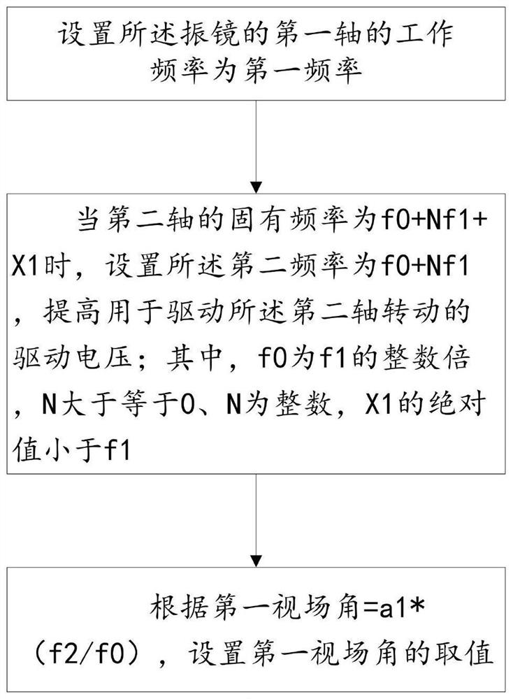
[0034] When the galvanometer is subjected to changes in the external environment, the frequency will change, mainly affected by temperature and amplitude. In terms of physical properties, metals have thermal expansion and contraction, and Young's modulus has a temperature coefficient. The frequency of the galvanometer increases when the temperature increases, and decreases when the temperature ...


PUM


Abstract

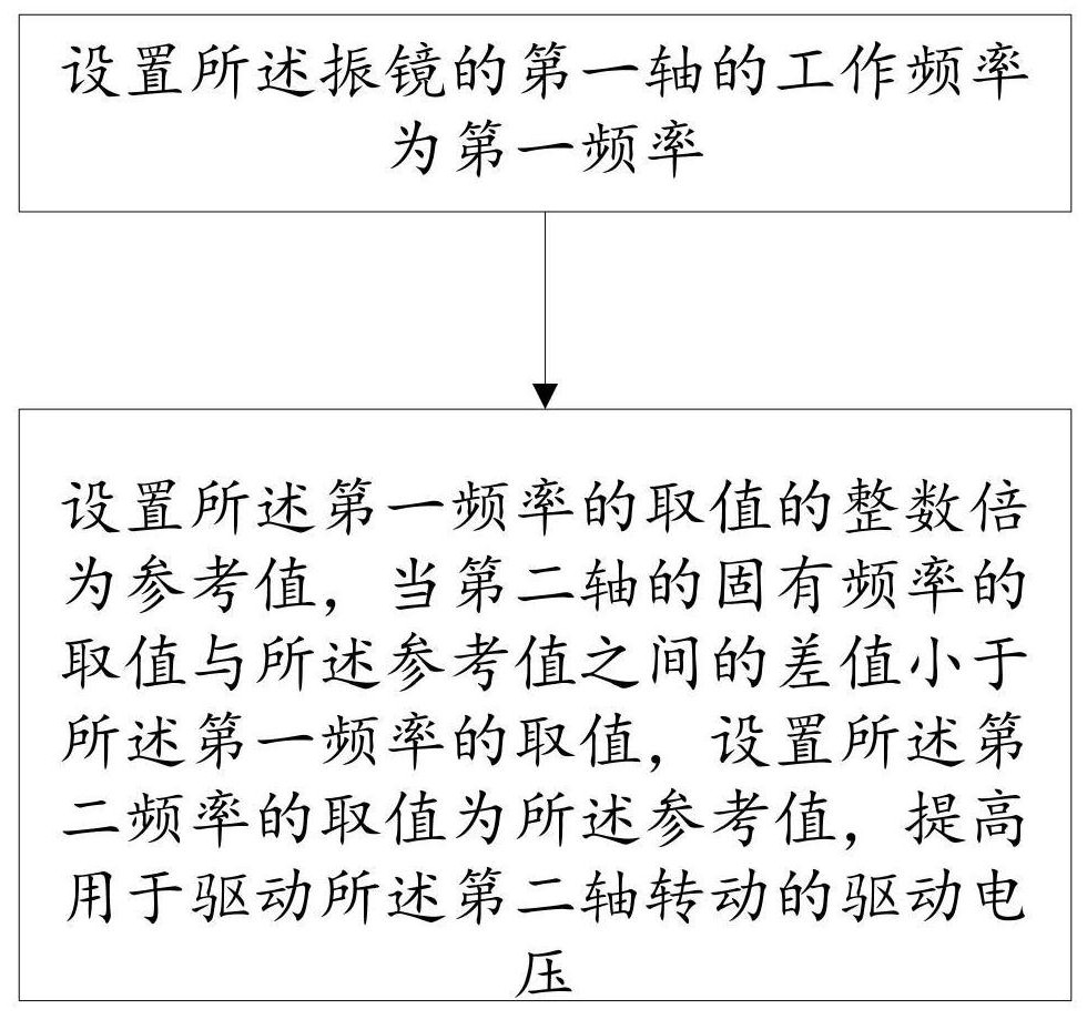
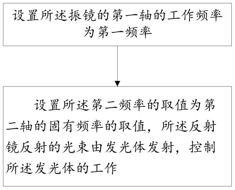
A galvanometer and a constant resolution-based galvanometer control method. The galvanometer comprising: a reflecting mirror for reflecting light beams emitted by an illuminant; a first shaft having a working frequency of a first frequency; and a second shaft having a working frequency of a second frequency, the second frequency being greater than the first frequency, the first shaft and the second shaft driving the reflecting mirror of the galvanometer to deflect, and the rotation axis of the second shaft being perpendicular to the rotation axis of the first shaft. Said method comprises: setting an integer multiple of the value of the first frequency as a reference value, and when the difference between the value of the natural frequency of the second shaft and the reference value is less than the value of the first frequency, setting the value of the second frequency as the reference value, for increasing the driving voltage for rotating the second shaft; or, setting the value of the second frequency as the value of the natural frequency of the second shaft, for changing the working state of the illuminant for emitting light beams to the reflecting mirror.

Description

Technical field [0001] The invention belongs to the field of optical detection, and particularly relates to a galvanometer and a galvanometer control method based on a constant resolution. Background technique [0002] In order to achieve rapid and accurate detection, the galvanometer is placed in the light path and used to reflect the light beam emitted by the luminous body, and actively project the structured light onto the object to be measured. Etc.) to determine the size parameters of the measured object to achieve the accuracy and efficiency of scanning detection. [0003] However, the frequency of the existing galvanometer is affected by the environment, and the frequency change will affect the obtained image display, reduce the accuracy of detection, and affect the effective judgment of the detection object. Summary of the invention [0004] In order to solve the technical problems in the prior art, the present invention proposes a galvanometer, including: [0005] Mirror, u...

Claims


Application Information

Patent Timeline
Patent Type & Authority Patents(China)
IPC IPC(8): G02B26/08
CPCG02B26/0833
Inventor 叶良琛向少卿
Owner HESAI TECH CO LTD
Why Eureka
Eureka Blog
Learn More