
Signal equipment fault diagnosis method and diagnosis system

A signal equipment and fault diagnosis technology, applied in the field of rail transit, can solve the problems of poor timeliness, labor-intensive manual analysis of monitoring data, and incompetence of manual analysis.

Active Publication Date: 2018-11-23
CHINA SHENHUA ENERGY CO LTD +1
View PDF6 Cites 2 Cited by
  • Summary
  • Abstract
  • Description
  • Claims
  • Application Information

AI Technical Summary

Problems solved by technology

However, the amount of data obtained through computer monitoring is very large, which leads to labor-intensive manual analysis of monitoring data and poor timeliness
Moreover, the analysis quality of this analysis method also varies from person to person. For example, in terms of capturing instantaneous changes, data correlation analysis, and comparative analysis of historical data, manual analysis is incompetent.

Method used


Image

  • Signal equipment fault diagnosis method and diagnosis system
  • Signal equipment fault diagnosis method and diagnosis system
  • Signal equipment fault diagnosis method and diagnosis system

Examples


Embodiment Construction

[0022] The specific implementation manners of the embodiments of the present invention will be described in detail below in conjunction with the accompanying drawings. It should be understood that the specific implementation manners described here are only used to illustrate and explain the embodiments of the present invention, and are not intended to limit the embodiments of the present invention.

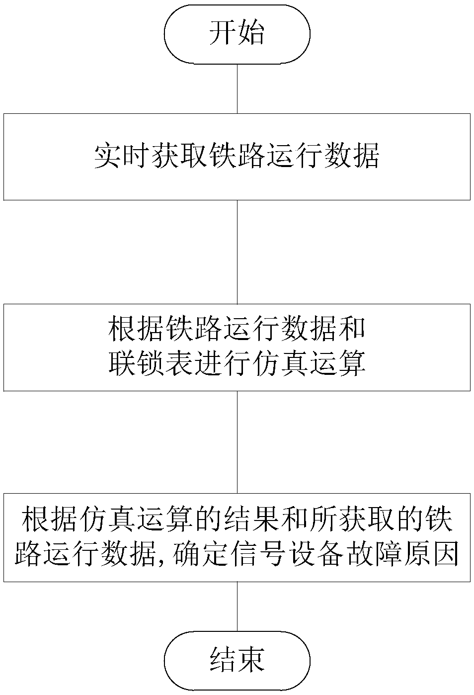
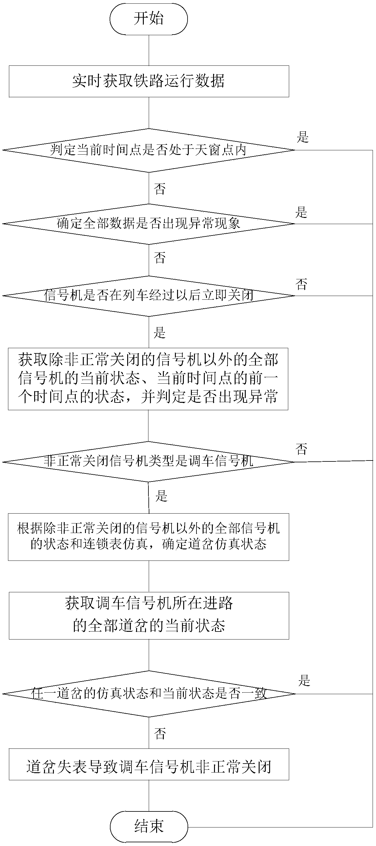
[0023] figure 1 It is a flowchart of a method for diagnosing a signal device fault provided by an embodiment of the present invention. Such as figure 1 As shown, the method includes: obtaining railway operation data in real time; performing simulation calculation according to the railway operation data and the interlocking table; and determining the cause of the failure of the signal equipment according to the result of the simulation calculation and the obtained railway operation data.

[0024] Among them, in the process of acquiring railway operation data in real time, data ca...


PUM


Abstract

The embodiment of the invention provides a signal equipment fault diagnosis method and fault diagnosis system, and belongs to the technical field of rail traffic. The diagnosis method comprises the steps that railway operation data is acquired in real time; simulation calculation is conducted according to the railway operation data and an interlocking table; and the signal equipment fault reason is determined according to a result of simulation calculation and the acquired railway operation data. According to the technical scheme, the signal equipment fault reason can be quickly and accuratelydetermined, the working efficiency is improved, and the interference to railway transportation by faulty signal equipment is reduced.

Description

technical field [0001] The invention relates to the technical field of rail transit, in particular to a signal equipment fault diagnosis method and a diagnosis system. Background technique [0002] In the prior art, the computer monitors the data related to train operation, and manually analyzes the data and the generated curves one by one to identify pathological data, thereby achieving the purpose of preventing or solving the failure of signal equipment. However, the amount of data obtained through computer monitoring is very large, which makes manual analysis of monitoring data labor-intensive and poor in timeliness. Moreover, the analysis quality of this analysis method also varies from person to person. For example, in terms of capturing instantaneous changes, data correlation analysis, and comparative analysis of historical data, manual analysis is incompetent. Contents of the invention [0003] The purpose of the embodiment of the present invention is to provide a ...

Claims


Application Information

Patent Timeline
IPC IPC(8): G06F17/50
CPCG06F30/20
Inventor 尹明苏有斌吕红白宏权
Owner CHINA SHENHUA ENERGY CO LTD
Learn More