Physics teaching tool for demonstration of horizontal projectile motion

A technology of flat throwing and movement, applied in the field of physical teaching aids for flat throwing movement demonstration, can solve problems such as simplicity, impact on teaching quality, and incomplete demonstration effects, and achieve the effect of ensuring teaching quality and comprehensive effects

Inactive Publication Date: 2018-11-23
南京溧水高新产业股权投资有限公司
View PDF9 Cites 6 Cited by
  • Summary
  • Abstract
  • Description
  • Claims
  • Application Information

AI Technical Summary

Problems solved by technology

[0003] However, the traditional flat-throw motion demonstrator is too simple to show the facts of motion more objectively during the demonstration, and...

Method used


Image

  • Physics teaching tool for demonstration of horizontal projectile motion
  • Physics teaching tool for demonstration of horizontal projectile motion
  • Physics teaching tool for demonstration of horizontal projectile motion

Examples


Embodiment 1

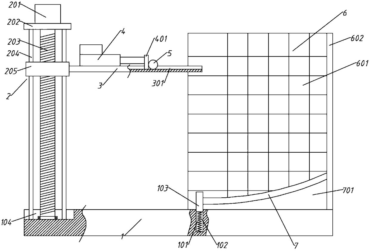
[0042] A physical teaching aid for electromagnetic induction demonstration, comprising a base 1, a lifting component 2, a flat throwing component and a demonstration board 6;

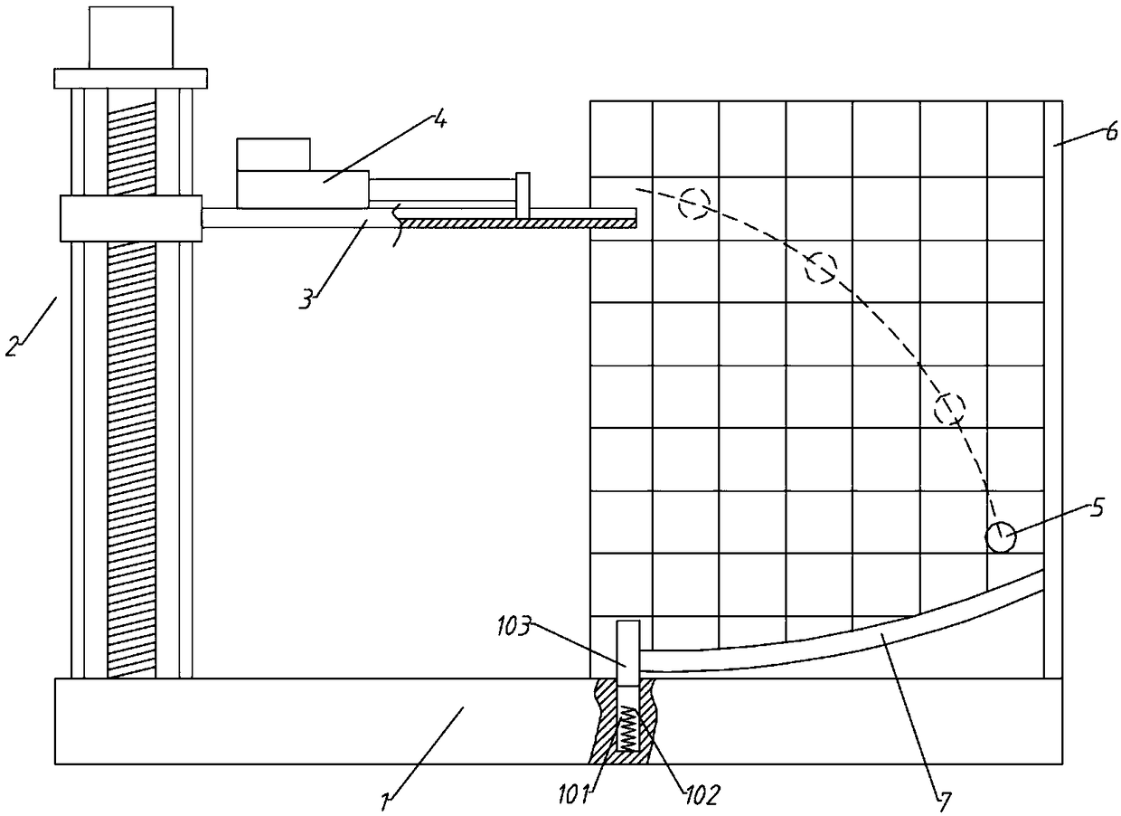
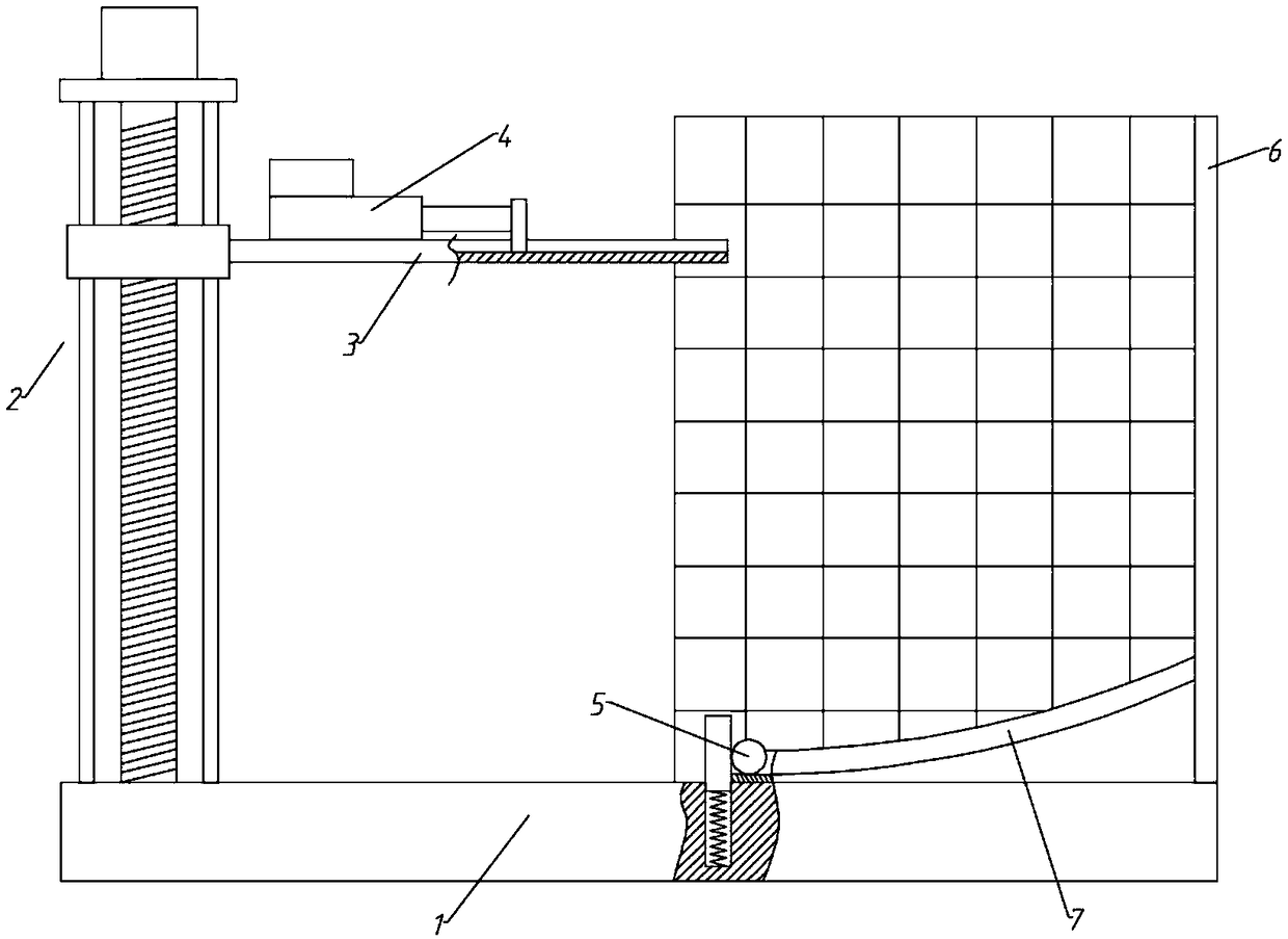
[0043] The lifting assembly 2 is arranged on the left end of the base 1, the flat throwing assembly includes a transverse plate 3, an electric push rod 4 and a No. 1 ball 5, the left end of the transverse plate 3 is connected to the lifting assembly 2, and a horizontal slideway 301 is arranged on the transverse plate 3, The electric push rod 4 is arranged on the left end of the horizontal slideway 301, and the telescopic end of the electric pushrod 4 stretches out to the right and is connected with a push plate 401. The No. 1 ball 5 is arranged in the horizontal slideway 301, and the push plate 401 pushes the small ball along the horizontal slideway 301. Horizontal slideway 301 moves;

[0044] The demonstration board 6 is arranged on the right end of the base 1, the demonstration board 6 is provided wit...

Embodiment 2

[0049] The difference from Embodiment 1 is that the lifting assembly 2 includes a driving motor 201, a top plate 202, a screw mandrel 203, a moving nut 205 and a guide rod 204. The top plate 202 is arranged above the left end of the base 1 and fixed by the vertical guide rod 204 Connected to the left end of the base 1, the driving motor 201 is arranged on the top plate 202, the output shaft of the driving motor 201 protrudes downwards and connects to the screw rod 203, the bottom end of the screw rod 203 is connected to the base 1 by rotation, and the moving nut 205 is screwed on the screw rod 203 And it is passed by the guide rod 204, and the left end of the transverse plate 3 is connected with a moving nut 205.

[0050] Utilizing the movement characteristics of the screw rod 203, the vertical movement of the horizontal plate 3 is realized, and the initial height and initial speed of the No. 1 ball 5 are conveniently adjusted.

Embodiment 3

[0052] The difference from Embodiment 2 is that the left end of the base 1 is provided with a groove 104 , and the bottom end of the lifting assembly 2 is arranged in the groove 104 to ensure the movement range of the transverse plate 3 .


PUM


Abstract

The invention specifically relates to a physics teaching tool for the demonstration of horizontal projectile motion, and the teaching tool employs a screw assembly as a lifting assembly to drive a horizontal projectile assembly to move up and down, thereby achieving the adjustment of the initial height of the horizontal projectile motion of a small ball. An electric push rod is employed as a source of the power of the small ball for achieving the adjustment of the initial speed of the horizontal projectile motion of the small ball. The teaching tool is complete in demonstration effect of the horizontal projectile motion experiment, and guarantees the teaching quality. A pedestal is provided with a spring support-type separator plate. When the horizontal projectile assembly moves downwards,the separator plate is pressed into a slot, and the small ball blocked by the separator plate is released, and slides to a horizontal slideway; and then the lifting assembly lifts a lateral plate toa certain height again for next horizontal projectile motion, and the separator plate is stretched out again under the action of the spring, and continues to block the small ball. Moreover, the teaching tool is additionally provided with a simple harmonic swinging demonstration assembly and a control assembly. When a first ball falls to a roll-back slideway, the teaching tool controls an electromagnet to release an absorbed second small ball through sensing the weight changes of the roll-back slideway and performs the swinging motion demonstration, thereby improvignthe teaching extensibility.

Description

technical field [0001] The invention relates to the technical field of physics teaching aids, in particular to a physics teaching aid for flat throwing motion demonstration. Background technique [0002] The object is thrown horizontally with a certain initial velocity. If the object is only affected by gravity, this kind of motion is called flat throwing motion. The motion of flat throwing can be regarded as the combined motion of uniform linear motion in the horizontal direction and free fall motion in the vertical direction. The object in flat throwing motion, because the resultant external force it receives is a constant force, so the flat throwing motion is a uniform speed curve motion, and the motion trajectory of the flat throwing object is a parabola. The flat throwing motion is a curved motion. The time of the flat throwing motion is only related to the vertical height of the throwing point; the horizontal displacement of the object on the ground is related to the ...

Claims


Application Information

Patent Timeline
IPC IPC(8): G09B23/10
CPCG09B23/10
Inventor 陈继珍
Owner 南京溧水高新产业股权投资有限公司
Why Eureka
Try Eureka