Medium-pressure air-insulated sealed switch cabinet

An air-insulated, switchgear technology, applied in switchgear, switchgear settings, electrical components, etc., can solve problems such as mechanism can not work normally, reduce the insulation strength in the cabinet, reduce product reliability, etc., to maintain the level of insulation strength , Improve the ability to resist phase-to-phase faults and maintain the effect of dielectric strength

Inactive Publication Date: 2018-11-23
ANHUI LIANNENG ELECTRICAL APPLIANCE
View PDF0 Cites 0 Cited by
  • Summary
  • Abstract
  • Description
  • Claims
  • Application Information

AI Technical Summary

Problems solved by technology

[0002] The sealed switchgear on the market is mainly aimed at the problem that the internal mechanism of the switchgear cannot work normally due to the infiltration of moisture or dust due to the lack of sealing after the gas-insulated sealed cabinet has been running for a period of time; because of the rainy season, the humidity in the switchgear is high Therefore, the humidity sensor and automatic heating and dehumidification device are installed in the switch cabinet, and the above-mentioned "condensation" problem is solved through the cooperation of the humidity sensor and the automatic heating and dehumidification device. This will not only increase the manufacturing cost, but also because it is easy to Damaged components enter the switch sealed cabinet and seriously reduce the reliability of the product, while most air-insulated switch cabinets with non-sealed structures are designed with door gaps, or there are gaps at the joints of all sides of the cabinet, metal dust, pollution The gas will enter the switch cabinet through these gaps due to gas convection, not only covering the main conductor to affect heat dissipation, but also reducing the insulation strength inside the cabinet under humid conditions, which will bring huge safety hazards such as pollution flashover

Method used


Image

  • Medium-pressure air-insulated sealed switch cabinet
  • Medium-pressure air-insulated sealed switch cabinet
  • Medium-pressure air-insulated sealed switch cabinet

Examples


Embodiment Construction

[0013] The present invention will be further described below with reference to the drawings and embodiments.

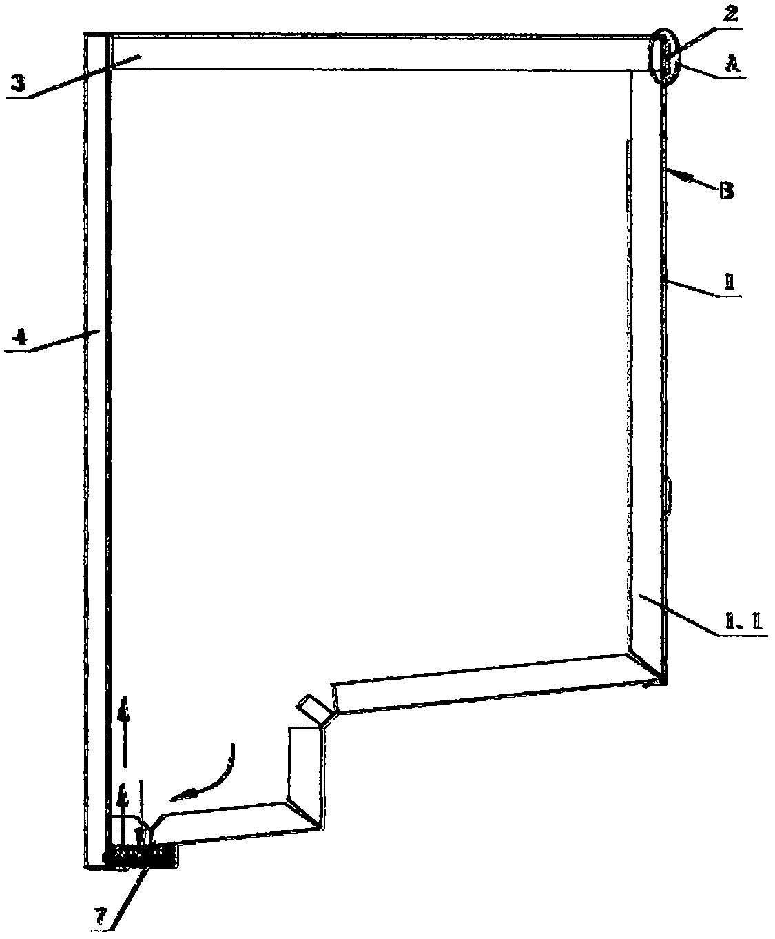
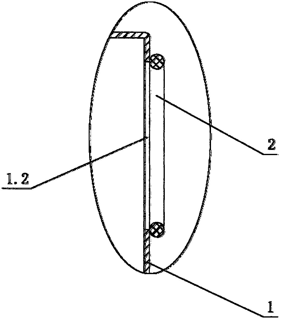
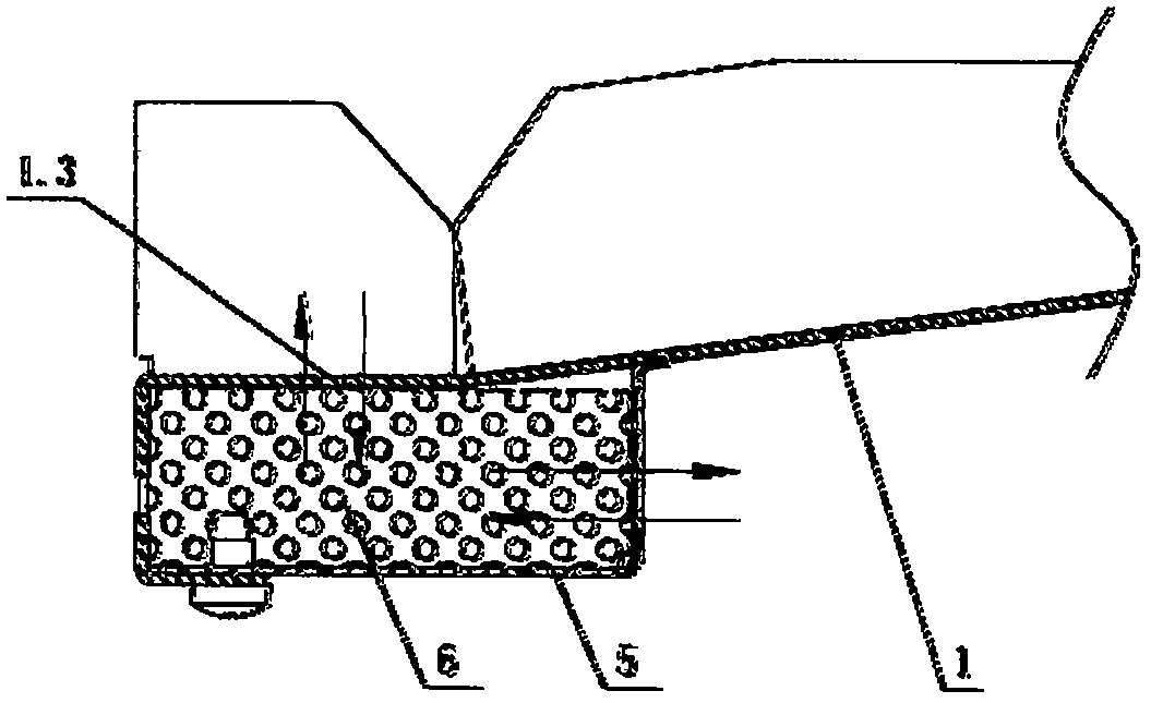
[0014] See Figure 1-Figure 3 , This medium-pressure air-insulated sealed switchgear includes a front panel 1, left and right side panels and a rear panel 4. The front panel 1, left and right side panels and the rear panel 4 are spliced ​​with each other and fixed by fasteners, the front panel 1, left and right The side panel and the rear panel 4 are provided with a bending short side 1.1 and / or a corner panel, and a joint sealing area is formed by bending the short side 1.1 and / or the corner plate, and the switch cabinet is sealed by the seam A sealant is set on the top to form a permanently fixed and statically sealed box structure; the switch cabinet is also provided with a natural pressure relief balanced vent channel 7 that realizes the principle of self-balancing the internal and external air pressure of the sealed switch cabinet, so that the switch cabinet has a n...


PUM


Abstract

The invention relates to a medium-pressure air-insulated sealed switch cabinet. The medium-pressure air-insulated sealed switch cabinet comprises a front plate, left and right side plates and a rear plate. The front plate, the left and right side plates and the rear plate are mutually spliced and fixed by fasteners, bending short edges and / or corner plates are arranged between the front plate, theleft and right side plates and the rear plate, a joint sealing area is formed by bending short edges and / or the corner plates, and the switch cabinet is provided with sealant on the joint sealing area to form a box structure with permanent fixed static sealing. The switch cabinet is further provided with a natural pressure relief balance ventilation channel groove for realizing the principle of self-balance of internal and external air pressure of the sealed switch cabinet, so that the switch cabinet has the natural pressure relief balance capability. After a main electric conductor in the switch cabinet is electrified, the temperature in the cabinet rises, and the air in the cabinet with slight positive pressure after being heated and expanded is released from the natural pressure reliefbalance ventilation channel groove to the outside until the pressure inside and outside the switch cabinet is equal, and no air convection exists inside and outside the switch cabinet, the purpose ofnatural isolation from metal dust and filth is achieved.

Description

Technical field [0001] The invention relates to a medium-voltage air-insulated and sealed switchgear, in particular to a medium-voltage air-insulated and sealed switchgear with natural pressure relief and balance capabilities. Background technique [0002] The sealed switchgear on the market now mainly aims at the problem that the internal mechanism of the switchgear cannot work normally due to the lack of sealing, moisture or dust entering after a period of operation of the gas insulated sealed cabinet; because the humidity in the switchgear is high due to the rainy season. "Condensation" is formed. Therefore, the humidity sensor and automatic heating and dehumidification device are installed in the switch cabinet, and the above-mentioned "condensation" problem is solved through the cooperation of the humidity sensor and automatic heating and dehumidification. This not only increases the manufacturing cost, but also because it is easy to Damaged components enter the switch cabin...

Claims


Application Information

Patent Timeline
IPC IPC(8): H02B13/035H02B13/025
CPCH02B13/035H02B13/025
Inventor 王毕胜
Owner ANHUI LIANNENG ELECTRICAL APPLIANCE
Why Eureka
Try Eureka