Two-axis anti-shaking pan-tilt and camera device

An anti-shake and pan-tilt technology, applied in the field of photography, can solve problems such as limiting the anti-shake angle and not being suitable for the pan-tilt

Pending Publication Date: 2018-11-23
TRULY OPTO ELECTRONICS
View PDF1 Cites 25 Cited by
  • Summary
  • Abstract
  • Description
  • Claims
  • Application Information

AI Technical Summary

Problems solved by technology

But strictly speaking, during the anti-shake process, the camera module 1' does not actually rotate around the X-axis and Y-axis, but tilts (Tilt) toward the X-axis and Y-axis, because under the interaction force of the magnetic field , the camera

Method used


Image

  • Two-axis anti-shaking pan-tilt and camera device
  • Two-axis anti-shaking pan-tilt and camera device
  • Two-axis anti-shaking pan-tilt and camera device

Examples


Embodiment 1

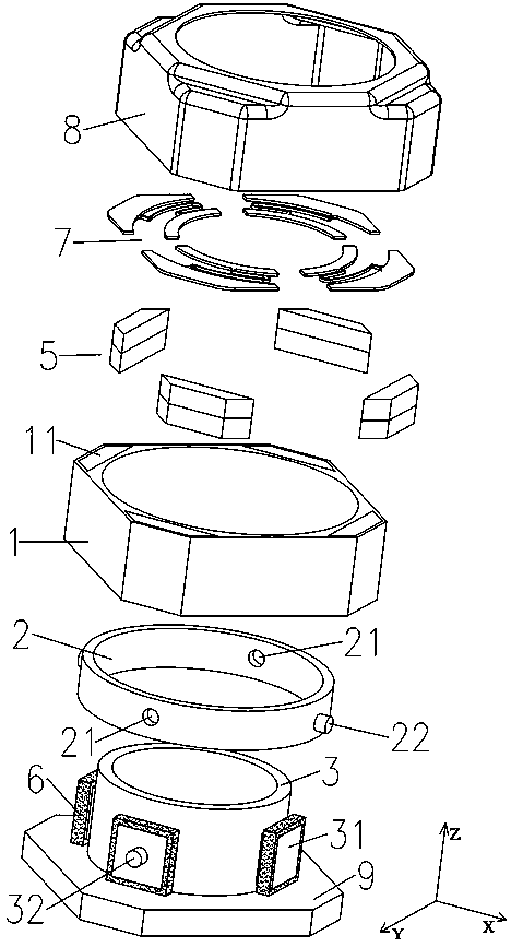
[0029] Such as Figure 2-4 As shown, a two-axis anti-shake head includes an outer bracket 1, a middle bracket 2 and an inner bracket 3 arranged sequentially from outside to inside, wherein

[0030] The outer bracket 1 is used as a fixing part and is provided with a first magnetic element group;

[0031] The middle bracket 2 is used as a rotating part around the X axis, and is pivotally connected to the outer bracket 1;

[0032] The inner bracket 3 is used as a rotating member around the Y axis and a carrier of the camera module 4, and is axially connected to the middle bracket 2, and is provided with a first magnetic element group;

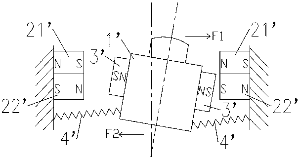
[0033] The magnetic field interaction force between the first magnetic element group and the second magnetic element group drives the middle bracket 2 to rotate around the X axis relative to the outer bracket 1, and drives the inner bracket 3 to rotate relative to the outer bracket 1 The middle bracket 2 rotates around the Y axis, and the orthog...

Embodiment 2

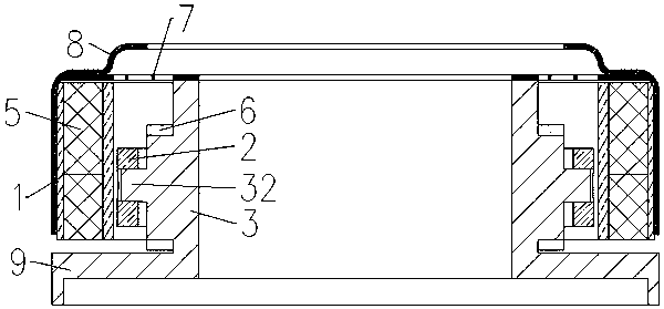
[0044] Such as Figure 5 As shown, a camera device includes the two-axis anti-shake pan-tilt described in Embodiment 1 and a camera module 4 , and the camera module 4 is assembled in the inner bracket 3 .

[0045] Specifically, the camera module 4 includes a lens 41 and a PCB 43 equipped with a photosensitive chip 42, the lens 41 is arranged on the cylindrical interior of the inner support 3, and the PCB 43 is arranged on the On the back side of the base 9 at the lower end of the inner support 3 .


PUM


Abstract

The invention discloses a two-axis anti-shaking pan-tilt and a camera device. The two-axis anti-shaking pan-tilt comprises an outer-layer support, a middle-layer support and an inner-layer support arranged sequentially from outside to inside, wherein the outer-layer support is used as a fixing piece and is provided with a first magnetic component group; the middle-layer support is used as a rotating piece around an X axis and is axially connected in the outer-layer support; the inner-layer support is used as a rotating piece around a Y axis and a bearing piece for a camera module, is axially connected in the middle-layer support and is provided with a second magnetic component group; and the mutual acting force of a magnetic field between the first magnetic component group and the second magnetic component group drives the middle-layer support to rotate around the X axis relative to the outer-layer support and drives the inner-layer support to rotate around the Y axis relative to the middle-layer support, and orthographic projections of the X axis and the Y axis on an anti-shaking plane are orthographic. According to the two-axis anti-shaking pan-tilt, during the anti-shaking process, the camera module does not generate translation on the anti-shaking plane, rotation shaking prevention in the true sense can be realized, a larger anti-shaking angle is realized, and the two-axisanti-shaking pan-tilt and the camera device are applicable to a large-angle anti-shaking scene such as an unmanned aerial vehicle and a recorder.

Description

technical field [0001] The invention relates to the field of photography, in particular to a two-axis anti-shake platform and a photography device. Background technique [0002] The anti-shake gimbal is a device for carrying a camera module and performing optical anti-shake on the camera module. It is widely used in drones and selfie sticks. At present, most anti-shake gimbals adopt passive anti-shake in the form of shock absorption and active anti-shake in the form of movement. Active anti-shake in the form of movement generally uses servos or motors to drive the camera module to make a movement that is opposite to the vibration direction and has a similar amplitude. To counteract vibration, the cost is high, the weight is large and the structure is complicated. [0003] In a patent document whose publication number is CN107340667A, a kind of anti-shake micro-head is disclosed, which includes an inactive structure composed of a shell, a positioning seat and a magnet, and a...

Claims


Application Information

Patent Timeline
IPC IPC(8): H04N5/225H04N5/232G03B17/56
CPCG03B17/561H04N23/50H04N23/682H04N23/685
Inventor 谢荣富
Owner TRULY OPTO ELECTRONICS
Why Eureka
Try Eureka