Plug

A plug and sleeve technology, applied in the field of leak detection devices, can solve problems such as poor sealing effect, misjudgment of test, small contact surface, etc., and achieve good sealing performance, convenient operation and high efficiency

Active Publication Date: 2021-08-06
SHINRY TECH
View PDF5 Cites 0 Cited by
  • Summary
  • Abstract
  • Description
  • Claims
  • Application Information

AI Technical Summary

Problems solved by technology

However, the contact between the rubber cone plug and the faucet is a circular line, the contact surface is small, the sealing effect is not good, and it is easy to cause misjudgment of the test

Method used


Image

  • Plug
  • Plug
  • Plug

Examples


Embodiment Construction

[0032] The technical solutions in the embodiments of the present application will be described below with reference to the drawings in the embodiments of the present application.

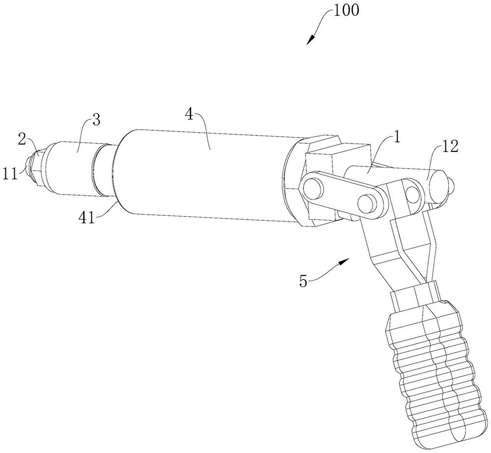
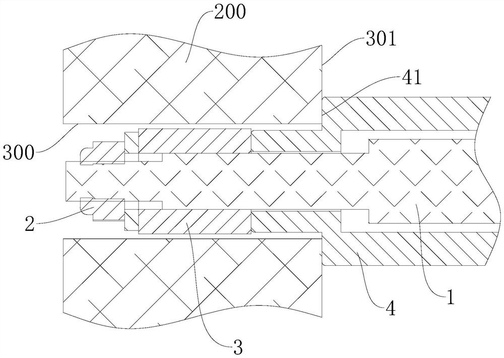
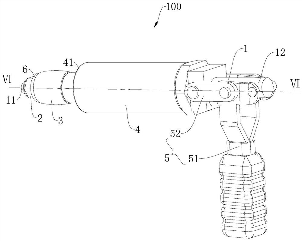
[0033] Please also refer to Figure 1 to Figure 6 , the embodiment of the present application provides a plug 100, and the plug 100 can be used to seal the channel 300 to be sealed of the housing 200 to be tested for leak tightness.

[0034] The plug 100 includes a main rod 1 , a pressing piece 2 , a sealing ring 3 , a sleeve 4 and a push-pull assembly 5 . The main rod 1 includes a first end 11 and a second end 12 oppositely disposed. The pressing member 2 is fixed on the first end 11 . The sealing ring 3 is slidingly sleeved on the outer peripheral side of the main rod 1 and located between the pressing member 2 and the second end 12 . The sleeve 4 is slidably sleeved on the outer peripheral side of the main rod 1 and located between the sealing ring 3 and the second end 12 . The outer peripher...


PUM


Abstract

A plug (100), comprising: a main rod (1), including a first end (11) and a second end (12) oppositely arranged; a pressing piece (2), fixed on the first end; a sealing ring (3 ), which is slidably set on the outer peripheral side of the main rod and is located between the pressure piece and the second end; the sleeve (4), which is slidably sleeved on the outer peripheral side of the main rod and is located between the sealing ring and the second end, and the outer circumference of the sleeve The side has a positioning end face (41) facing the pressing piece, when the pressing piece and the sealing ring extend into the channel to be sealed, the positioning end face abuts against the end face of the channel to be sealed; and a push-pull assembly (5), connected to the second end and the sleeve Between, it is used to drive the second end to move away from the casing, so that the pressing piece moves toward the casing and compresses the sealing ring, so that the radial dimension of the sealing ring increases and closely contacts with the channel to be sealed to form a sealing structure . The plug has good sealing effect.

Description

technical field [0001] The present application relates to the technical field of leak detection devices, in particular to a plug. Background technique [0002] In the production process of electronic assembly products with metal casings with water cooling channels, in order to ensure the sealing of the water channels, it is necessary to perform air pressure tightness testing on the metal casings with water channels. There are generally two faucets on the water channel of the shell, one for water inflow and one for water outflow. During the airtight test, one faucet needs to be blocked, and then high-pressure gas is poured into the other faucet to complete the water passage. Air tightness test to detect water leaks and air leaks. When blocking a faucet, a plug that can be plugged in quickly is needed. [0003] In the prior art, by making test equipment, a movable rubber conical plug is set at the position of the faucet to be blocked, and the faucet to be blocked is blocked ...

Claims


Application Information

Patent Timeline
Patent Type & Authority Patents(China)
IPC IPC(8): G01M3/02F16J15/00F16L55/128
CPCF16J15/00F16L55/128G01M3/02
Inventor 刘国仟李光显吴壬华
Owner SHINRY TECH
Why Eureka
Try Eureka