Electricity storage device and manufacturing method therefor
A technology of storage equipment and winding direction, which is applied in secondary battery manufacturing, hybrid/electric double layer capacitor manufacturing, final product manufacturing, etc., and can solve problems such as strict configuration space
- Summary
- Abstract
- Description
- Claims
- Application Information
AI Technical Summary
Problems solved by technology
Method used
Image
Examples
no. 1 Embodiment approach
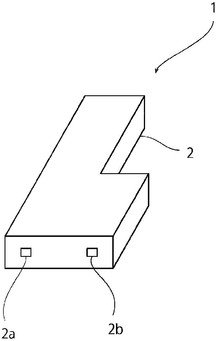
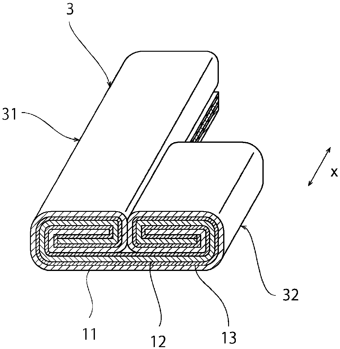
[0038] figure 1 It is a schematic perspective view of the electrical storage device concerning 1st Embodiment. figure 2 It is a schematic perspective view of the electrode body in 1st Embodiment.
[0039] figure 1 The shown power storage device 1 may be, for example, a battery such as a rechargeable battery, a capacitor such as an electric double layer capacitor, or the like.
[0040] Such as figure 1 As shown, the electrical storage device 1 includes a casing 2 . The casing 2 has a shape other than a rectangle when viewed from above. The shape of the casing 2 in plan view may be, for example, an L-shape, an H-shape, a U-shape, a T-shape, or the like. That is, in the present invention, the top view shape of the case may be any shape as long as it is not a rectangular shape.
[0041] The housing 2 may also be made of a conductor or an insulator. The case 2 can be made of, for example, metal such as aluminum, stainless steel, copper, laminated foil, resin, or the like. ...
no. 2 Embodiment approach
[0066] Image 6 It is a schematic perspective view of the electrode body in 2nd Embodiment.
[0067] Such as Image 6 As shown, in the second embodiment, the electrode body 3 has a first wound body 31 , a second wound body 32 , and a third wound body 33 . The second winding body 32 is connected to one end of the first winding body 31 in the winding axis direction (x-axis direction), and the third winding body 33 is connected to the first winding body 31 in the winding axis direction. (x-axis direction) the other end is connected. Therefore, the electrode body 3 has a substantially U-shape in plan view. By utilizing the electrode body 3 of the present embodiment, it is possible to realize a substantially U-shaped electrical storage device in a planar view.
[0068] In addition, the electrode body 3 of the present embodiment can be obtained by using, for example, Figure 7 The laminated body 4A shown was fabricated. The laminated body 4A has a first portion 4A1 extending i...
no. 3 Embodiment approach
[0070] Figure 8 It is a schematic perspective view of the electrode body in 3rd Embodiment.
[0071] Such as Figure 8 As shown, in the third embodiment, the electrode body 3 has a first wound body 31 and a second wound body 32 . The second wound body 32 is connected to the central portion of the first wound body 31 in the winding axis direction (x-axis direction). Therefore, the electrode body 3 has a substantially T-shape in plan view. By utilizing the electrode body 3 of this embodiment, it is possible to realize an electrical storage device having a substantially T-shape in plan view.
[0072] In addition, the electrode body 3 of the present embodiment can be used, for example, Figure 9 The laminated body 4B shown was fabricated. The laminate 4B has a first portion 4B1 extending in the x-axis direction, and a second portion 4B2 extending from the center of the first portion 4B1 in the x-axis direction toward the y-axis direction perpendicular to the x-axis direction...
PUM
 Abstract
Description
Claims
Application Information
 - R&D
- Intellectual Property
- Life Sciences
- Materials
- Tech Scout
- Unparalleled Data Quality
- Higher Quality Content
- 60% Fewer Hallucinations
Browse by: Latest US Patents, China's latest patents, Technical Efficacy Thesaurus, Application Domain, Technology Topic, Popular Technical Reports.
© 2025 PatSnap. All rights reserved.Legal|Privacy policy|Modern Slavery Act Transparency Statement|Sitemap|About US| Contact US: help@patsnap.com


