A load and conveying device for pap printing

A conveying device and paper technology, applied in the directions of transportation and packaging, object supply, pile separation, etc., can solve the problems of difficulty in feeding materials, inability to adjust the fixed height of the structure, etc., to speed up printing efficiency, facilitate transportation, and improve work efficiency.

Inactive Publication Date: 2018-11-27
BEITANG JUNZHI PRINTING PAPER PROCESSING FACTORY
View PDF0 Cites 3 Cited by
  • Summary
  • Abstract
  • Description
  • Claims
  • Application Information

AI Technical Summary

Problems solved by technology

[0004] The purpose of the present invention is to provide a support conveying device for paper printing to solve the problem that the fixed height of the structure cannot be adjusted and the feeding is difficult.

Method used


Image

  • A load and conveying device for pap printing
  • A load and conveying device for pap printing

Examples


Embodiment 1

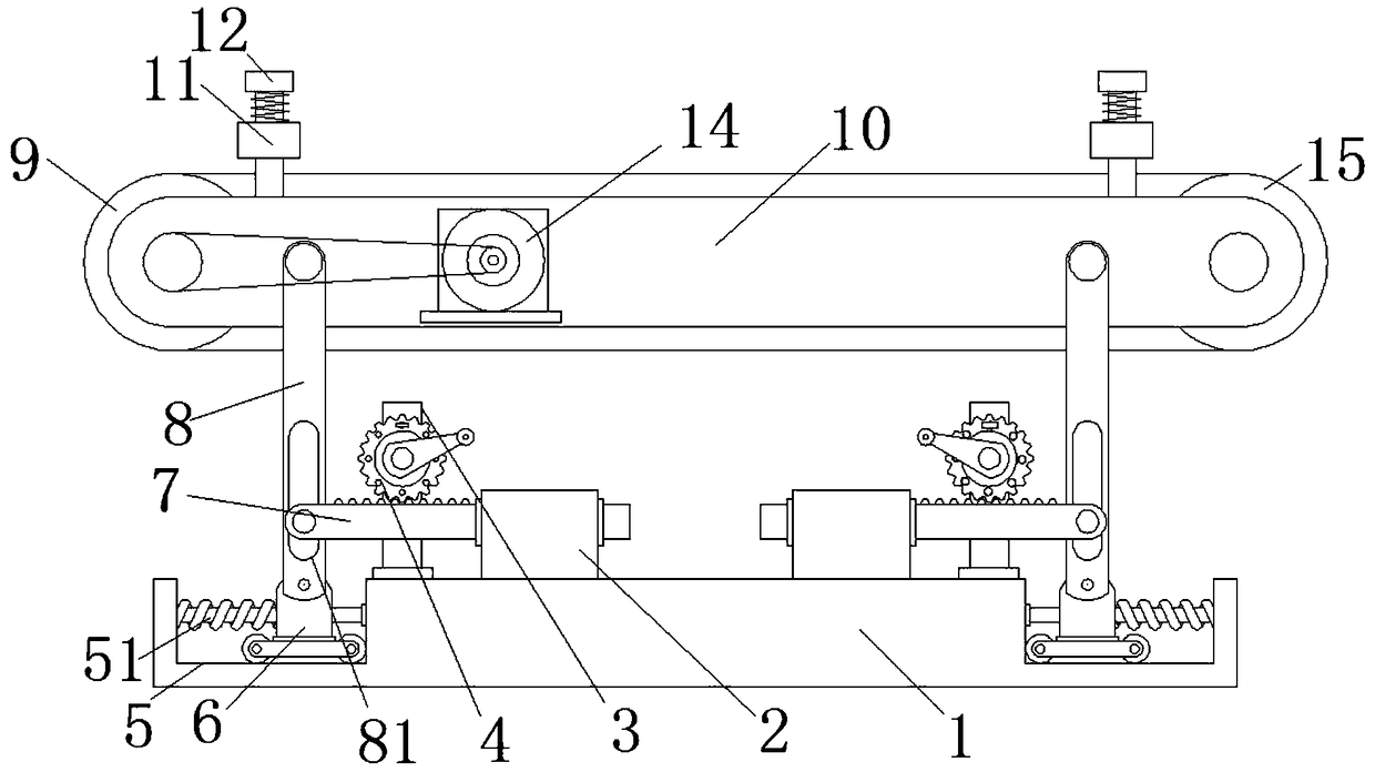
[0019] see Figure 1-2 , this embodiment provides a paper printing boosting conveying device, including a base 1, the top of the base 1 is fixedly connected with a mounting base 2 and a supporting base 3, the supporting base 3 is connected with a gear 4 through a rotating shaft, and the inner wall of the mounting base 2 slides A sliding rod 7 is connected, the top of the sliding rod 7 meshes with the gear 4 through the gear teeth, grooves 5 are opened on both sides of the base 1, the inner wall of the groove 5 is fixedly connected with a limit light rod 51, and a slider is slidably sleeved on the limit light rod 51 6. A movable rod 8 is hinged on the top of the slider 6, and a chute 81 is provided on the movable rod 8. The end of the slider 7 away from the mounting seat 2 is movably connected to the inner wall of the chute 81 through a rotating shaft, and the top of the movable rod 8 is connected to a Mounting frame 10, driven conveyor roller 15 and driving conveyor roller 9 a...

Embodiment 2

[0022] see Figure 1-2 , a further improvement has been made on the basis of Embodiment 1: the gear 4 is plugged on the support base 3 through a pin and a socket, so that after the height of the mounting frame 10 is adjusted, the mounting frame 10 can be made to The position is fixed to prevent shaking. The outer side of the slider 6 is connected to the inner wall of the groove 5 with a second spring arranged on the outer side of the limit light rod 51. Through the setting of the second spring, it is more convenient to return the slider 6 to its original position. easy.

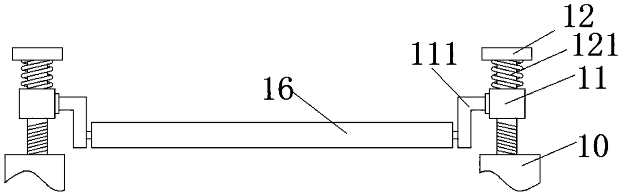
[0023] In the embodiment of the present invention, the bottom of the slider 6 is rollingly connected with the groove 5 through rollers, which can make the slider 6 slide better in the groove 5 and reduce friction. Tight roller 16 is when paper is pressed, avoids that pinch roller 16 is too hard and easily damages paper, and better protects paper, and the gear 4 is fixedly equipped with a hand lever, which is...


PUM


Abstract

A load and conveying device for pap printing including the base, A mount seat and a support seat are fixedly connected at the top of the base, A support seat is rotatably connecte with a gear througha rotating shaft, A sliding rod is slidably connecte with that inner wall of the mounting seat, A top portion of the slide bar is meshed with a gear through gear teeth, At both side of that base, grooves are arrange, A limit position light rod is fixedly connected with that inn wall of the groove, A slide block is slidably sleeved on the position limiting polish rod, A movable lever is hinged at the top end of the slider, a sliding groove is arranged on the movable lever, an end of the sliding lever far away from the mounting seat is movably connected to the inner wall of the sliding groove through a rotating shaft, and a mounting frame is rotatably connected at the top end of the movable lever through the rotating shaft, and a driven conveying roller and a driving conveying roller are rotatably installed on the mounting frame. The invention solves the problem that the feeding of the traditional paper conveying device is difficult, improves the working efficiency of the worker, facilitates the conveying of the paper, and at the same time can make the paper entering the printing press more even.

Description

technical field [0001] The invention relates to the technical field of paper printing equipment, in particular to a holding and conveying device for paper printing. Background technique [0002] Printing refers to the technology of transferring the ink to the surface of paper, fabric, leather and other materials through plate making, ink application, pressurization and other processes to reproduce the contents of the original manuscript in batches. There are many forms of printing, the most common ones are traditional offset printing, screen printing and digital printing. [0003] The clamping and conveying device is needed in the paper printing process, and the traditional clamping and conveying devices are mostly fixed in height, and the height and inclination angle of the conveying device cannot be adjusted according to people's needs. Moving paper from high to low or from low to high wastes a lot of physical strength of workers and affects their work efficiency. Conte...

Claims


Application Information

Patent Timeline
Patent Type & Authority Applications(China)
IPC IPC(8): B65H5/02
CPCB65H5/025B65H2404/256B65H2404/434B65H2801/21
Inventor 余学润
Owner BEITANG JUNZHI PRINTING PAPER PROCESSING FACTORY
Why Eureka
Try Eureka