Strong pressure type sludge deep dehydration system

A deep dehydration and sludge technology, applied in dehydration/drying/concentrated sludge treatment, filtration separation, separation methods, etc., can solve the problems of increasing compressible stroke, low energy consumption of strong pressure mechanical dehydration, difficult feeding, etc., to achieve Easy to unload, save manpower and time, good effect

Active Publication Date: 2015-04-08
JIANGSU ZHONGYI ECOLOGICAL SOIL INST +1
View PDF6 Cites 2 Cited by
  • Summary
  • Abstract
  • Description
  • Claims
  • Application Information

AI Technical Summary

Problems solved by technology

[0007] Due to the adoption of the above technical scheme, the sludge strong pressure deep dewatering system involved in the present invention, the piston grouting pump adopted is provided with a strong grouting pressure by the pneumatic pump station, which solves the problem of sludge with low water content (municipal dewatered sludge with a water content of 80 -90%) Difficult feeding; the inner ring body of the dehydration unit is movable in the outer ring body, so the dehydration unit has a shrinking function, which increases the compressible stroke of the sludge in the dehydration unit. Under the strong push of the hydraulic cylinder, it can High-pressure and strong dehydration is realized; a discharge plate is set in the inner ring of the dehydration unit, and the discharge plate realizes automatic discharge of dewatered sludge under the synergy of shrinking steel rods and manipulators; the continuous automatic operation of the entire dehydration system is realized, saving manpower and Time; the inner wall of the inner ring has a certain angle, which is convenient for unloading; the entire sludge strong pressure deep dewatering system is controlled by the control system, and the process is continuous and automatic, saving time and labor costs; the use of strong pressure mechanical dehydration consumes less energy and has better results , which reduces the cost of dehydration treatment and expands the subsequent disposal of sludge

Method used


Image

  • Strong pressure type sludge deep dehydration system

Examples


Embodiment Construction

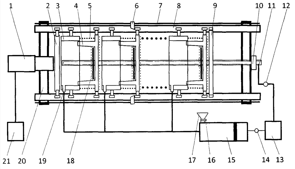
[0010] The present invention will be described in further detail below in conjunction with the accompanying drawings.

[0011] See the accompanying drawings, the sludge strong pressure deep dewatering system, the described sludge strong pressure deep dewatering system consists of a stroke bracket, a front top plate 2, a rear top plate 9, a shrinking steel rod 11, a piston grouting pump 15, a discharge plate 18 and two The dehydration unit arranged above is composed of the stroke bracket consisting of manipulator 6, guide rail 7, guide groove 8 and bracket 20. A pair of parallel guide grooves 8 are installed on the top surface of bracket 20. Guide rail 7 is arranged on the outside of guide groove 8. There is a manipulator 6, and the dehydration unit is composed of an outer ring body 3, an inner ring body 4, a limit chain 5 and a discharge plate 18. The inner ring body 4 and the outer ring body 3 are hollow, and one end of the inner ring body 4 is provided with a closed bottom pl...


PUM


Abstract

The invention relates to a strong pressure type sludge deep dehydration system, belonging to the technical field of environmental geotechnics. The strong pressure type sludge deep dehydration system is composed of a stroke support, a front top plate, a rear top plate, a shrinking steel rod, a piston grouting pump, a discharging plate and more than two arranged dehydrating units; According to the strong pressure type sludge deep dehydration system, the piston grouting pump is adopted to grout under strong pressure, so that a problem that sludge with low moisture content is difficultly fed is solved; the dehydrating units have shrinking functions and can realize sludge deep dehydration under strong pushing action of a hydraulic oil cylinder; the discharging plate can be used for discharging the dehydrated sludge automatically under the cooperative action of the shrinking steel rod and a mechanical arm; the whole system can realize continuous and automatic operation, and the time and labor costs are saved; and the strong pressure type mechanical dehydration mode is adopted, the energy consumption is low, the effect is good, the dehydration treatment cost is reduced and the follow-up sludge disposal way is expanded.

Description

technical field [0001] The invention relates to a sludge strong pressure deep dewatering system, which belongs to the technical field of environmental geotechnical engineering. Background technique [0002] With the rapid improvement of my country's sewage treatment capacity, sludge production has increased sharply. Relevant data show that in 2015, the national production of wet sludge (with a moisture content of about 83%) was nearly 40 million tons, with an average annual growth rate of more than 20%. Handling the situation is grim. [0003] The high moisture content of sludge is a key factor restricting the treatment and disposal of sludge. At present, the equipment used for sludge dewatering in sewage treatment plants in my country includes centrifugal dewatering machines, belt filter press sludge dewatering machines, plate and frame filter press dewaterers and diaphragm plate and frame filter press dewaterers. The dewatering centrifuge has high energy consumption, high...

Claims


Application Information

Patent Timeline
Patent Type & Authority Applications(China)
IPC IPC(8): B01D25/02C02F11/12
Inventor 陈亿军薛强许越王国菲孟思明
Owner JIANGSU ZHONGYI ECOLOGICAL SOIL INST
Why Eureka
Try Eureka