
Excavator one-hand control device

An excavator and hand-operated technology is applied in the field of excavator one-hand control devices to achieve the effects of saving training costs, increasing safety factor, and simple and easy-to-learn operation methods.

Active Publication Date: 2020-11-17
尹建新
View PDF8 Cites 0 Cited by
  • Summary
  • Abstract
  • Description
  • Claims
  • Application Information

AI Technical Summary

Problems solved by technology

[0004] However, with the traditional control method, the driver must have a high degree of coordination in both hands, so that he can better control the excavator for compound movements, and the driver needs a long period of training and practice to master the actual operation of the excavator. Hold

Method used


Image

  • Excavator one-hand control device
  • Excavator one-hand control device
  • Excavator one-hand control device

Examples


Embodiment 1

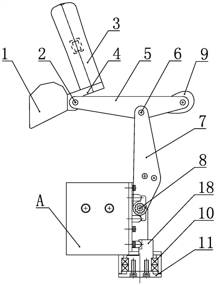
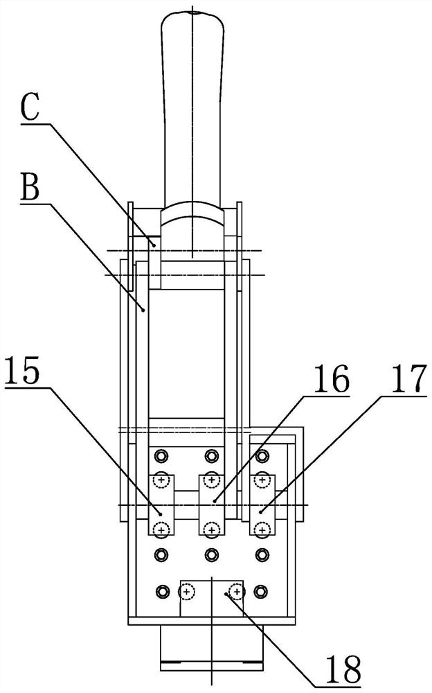
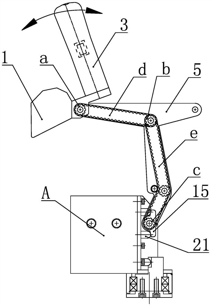
[0034] Such as figure 1 and 2 As shown, a single-handed control device for an excavator includes a bucket model 1, an arm model 5 and a boom model 7 that are sequentially connected in turn, wherein the bucket model 1 is provided with a handle 3, and the bucket model 1 and the arm The first rotating pin 2 is arranged between the models 5, the second rotating pin 6 is arranged between the arm model 5 and the boom model 7, and the device also includes a mounting base 11 on which a valve group is rotatably installed. Seat A, the end of the boom model 7 away from the arm model 5 is rotationally connected with the valve group seat A through the third rotating pin 8, and the valve group seat A is equipped with a bucket pilot valve, an arm pilot valve, and a boom pilot valve and rotary pilot valve, and are equipped with bucket spool briquetting block 15, arm spool briquetting block 16, boom spool briquetting block 17 and rotary spool briquetting block 18, wherein rotary spool briquet...

Embodiment 2

[0046] Such as Figure 8 and 9 As shown, this embodiment is an alternative structure of the first linkage part B and the second linkage part C in Embodiment 1, wherein the first linkage part B includes the sixth synchronous wheel i and the second The seventh synchronous wheel j on the rotating pin 6, the fourth synchronous belt k is set on the sixth synchronous wheel i and the seventh synchronous wheel j, and the end surface of the seventh synchronous wheel j is provided with a first A rocker arm m, the first rocker arm m is connected to the bucket valve core pressing block 15 through a first connecting rod n. With this structure, when the bucket model 1 rotates, the rotation of the bucket model 1 can also be sequentially transmitted to the bucket valve core pressure block 15 through the fourth synchronous belt k, the first rocker arm m and the first connecting rod n, and the bucket The bucket valve core pressing block 15 rotates around the third rotating pin 8 .

[0047] S...


PUM


Abstract

The invention discloses a one-handed control device for an excavator, which comprises a bucket model, an arm model and a boom model which are sequentially connected in rotation, a handle is arranged on the bucket model, and the boom model is connected to a valve group seat in rotation, and the valve There are bucket pilot valves, stick pilot valves, boom pilot valves and swing pilot valves built into the group seat to control the actions of the excavator bucket, stick, boom and body respectively. The four valves are respectively equipped with shovel pilot valves. Bucket spool briquetting block, arm spool briquetting block, boom spool briquetting block and rotary spool briquetting block; the bucket model can drive the bucket spool briquetting block through the first linkage part, and the stick model can drive the action of the bucket spool briquetting block through the second linkage The linkage parts can drive the action of the stick valve core pressing block. The rotation of the boom model around the valve group seat can drive the movement of the boom valve core pressing block. When the valve group seat rotates around the installation base, the rotary valve core pressing block can drive The rotary pilot valve works. The driver can control the excavator with one hand, and the operation method is simple and easy to master.

Description

technical field [0001] The invention relates to an excavator operating mechanism, in particular to an excavator single-handed control device. Background technique [0002] The current excavator has always been operated with both hands. The principle is to pull the handle to control the proportional pilot valve to output pilot hydraulic oil to push the main valve core. The larger the handle is pulled, the greater the pressure of the pilot hydraulic oil, and the main valve core moves The larger the amount, the more hydraulic oil the main valve outputs, and the faster the actuator (oil cylinder, hydraulic motor) moves. [0003] When the hydraulic excavator is working, there are mainly 8 actions, namely, digging and turning of the bucket; swinging back and forth of the stick; swinging back and forth of the boom; and rotating the fuselage left and right. There is a handle on both sides of the driver's seat, and there are 4 proportional pilot valves under each handle. The front a...

Claims


Application Information

Patent Timeline
Patent Type & Authority Patents(China)
IPC IPC(8): E02F9/20
CPCE02F9/20
Inventor 尹建新张德意
Owner 尹建新
Learn More