Convenient control type electronic lathe
An electronic and convenient technology, applied in the direction of large fixed members, metal processing machinery parts, metal processing equipment, etc., can solve the problem of complex operation of the transmission mechanism
- Summary
- Abstract
- Description
- Claims
- Application Information
AI Technical Summary
Problems solved by technology
Method used
Image
Examples
Embodiment
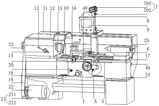
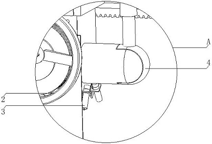
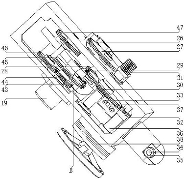
[0035] see Figure 1-4 , the present invention provides a technical solution: a conveniently operated electronic lathe, including a sliding board box 1, a vertical and horizontal reversing detection switch 3, a vertical and horizontal joystick 4, a rack 5, a vertical and horizontal sliding board 6, a numerical control system 9, and an electrical cabinet 11. Spindle box 12, spindle gear shift handle 13, spindle gear detection switch 14, spindle 15, tool holder 16, X handwheel 17, forward and reverse control switch 18, feed motor 19, emergency stop button 20, spindle Motor 21, transmission belt 22, spindle encoder 23, bed 24, tailstock 25, motor gear 26, first gear 27 of axis I, second gear 28 of axis I, axis I 29, first gear 30 of axis II, axis II 31. III shaft gear 32, positive and negative direction detection switch 33, quick shift button 34, positive and negative direction control handle 35, III shaft 36, positive and negative direction detection block 37, reversing lever 39...
PUM
 Abstract
Description
Claims
Application Information
 - R&D
- Intellectual Property
- Life Sciences
- Materials
- Tech Scout
- Unparalleled Data Quality
- Higher Quality Content
- 60% Fewer Hallucinations
Browse by: Latest US Patents, China's latest patents, Technical Efficacy Thesaurus, Application Domain, Technology Topic, Popular Technical Reports.
© 2025 PatSnap. All rights reserved.Legal|Privacy policy|Modern Slavery Act Transparency Statement|Sitemap|About US| Contact US: help@patsnap.com


