
Insulator string lifter

An insulator string and lifter technology, applied in the direction of overhead line/cable equipment, etc., can solve the problems of difficult handling of the external structure of the insulator string, safety accidents of staff, long working time, etc. Danger-reducing effect

Inactive Publication Date: 2017-01-11
成都捷科菲友信息技术有限公司
View PDF6 Cites 0 Cited by
  • Summary
  • Abstract
  • Description
  • Claims
  • Application Information

AI Technical Summary

Problems solved by technology

[0003] Porcelain, glass, and composite insulators are widely used in domestic power transmission and transformation projects. In the traditional installation process, it is very inconvenient to install the insulator string. Due to the heavy weight of the insulator string, it is very difficult to install the insulator string on a high tower. Since the external structure of the insulator string is not easy to carry, the staff need to further adjust the direction and angle of the insulator string during installation. The operation time is long and the procedure is complicated, and the staff are prone to safety accidents due to physical overdraw

Method used


Image

  • Insulator string lifter

Examples


Embodiment 1

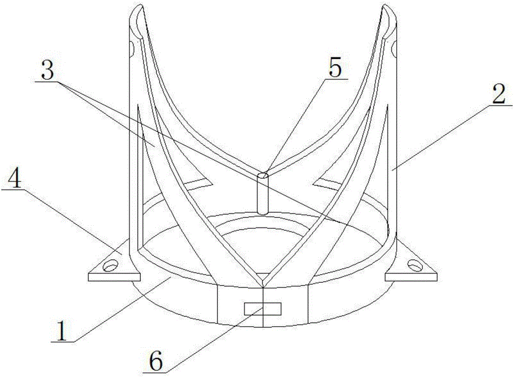
[0017] The main structure of the insulator string lifter of the present embodiment, such as figure 1 As shown, including the base 1, the upper surface of the base 1 is concaved into a groove matching the porcelain skirt of the insulator, the bottom of the groove is provided with a through hole matching the insulator, the upper left and right sides of the base 1 are fixed with hanging bars 2, and the hanging bars 2 The upper part is provided with a hanging hole, and the hanging bar 2 and the base 1 are also connected with at least one balance bar 3, the balancing bar 3 is fixed on the edge of the base 1, and the two sides of the base 1 opposite to the hanging bar 2 are respectively provided with hinges 5 and buckle6.

[0018] The specific implementation method is to open the buckle 6 of the base 1, open the base 1 through the hinge, and then nest the insulator porcelain skirt in the groove of the base 1, the lower part is stuck through the through hole in the base 1, and the ba...

Embodiment 2

[0020] In this embodiment, on the basis of the above-mentioned embodiments, it is further defined that the suspension bar 2 is connected to the base 1 through two balance bars 4 , and the planes where the hinges 5 and buckles 6 of the left and right suspension bars 2 are located are mirror images. Other parts of this embodiment are the same as those of Embodiment 1, and will not be repeated here.

Embodiment 3

[0022] In this embodiment, on the basis of the above embodiments, it is further defined that the outer side of the base 1 on which the hanging bars 2 are fixed is provided with a fixing block 4, and the fixing block 4 is provided with a fixing hole. Other parts of this embodiment are the same as those of Embodiment 1, and will not be repeated here.


PUM


Abstract

The invention discloses an insulator string lifter which comprises a base. The upper surface of the base is inwardly indented to form concave grooves that match the insulator porcelain dresses. The bottoms of the concave grooves are provided with through holes that match the insulators. The left side and the right side at the upper part of the base are fixedly provided with suspension strips. The suspension strips are provided with suspension holes. At least one balance strip is provided to connect the suspension strips with the base. The balance strip is fixedly arranged at the edge of the base. The two sides of the base relative to the suspension strips are provided with a hinge and a buckle respectively. With the designed structure, an insulator string can be easily fixed, which greatly reduces the hazard and the workload of the work staff. In addition, the labor intensity can also be reduced while the working efficiency is increased. In terms of insulator string installation, it becomes an easier and faster learning process, which can be mastered rapidly. All these advantages enable the lifter to be widely applied in the installation of various insulator strings. Simple in structure and cost-effective, the lifter provides practical performances in itself as well.

Description

technical field [0001] The invention relates to an auxiliary tool for installing and testing electric facilities, in particular to an insulator string lifter. Background technique [0002] With the construction and renovation of urban and rural power grids, the Three Gorges Project, the West-to-East Power Transmission and the start of railway construction projects, as well as the national cross-regional UHV network to be constructed, more UHV and EHV transmission lines will appear. The development of the insulator industry brings opportunities. [0003] Porcelain, glass, and composite insulators are widely used in domestic power transmission and transformation projects. In the traditional installation process, it is very inconvenient to install the insulator string. Due to the heavy weight of the insulator string, it is very difficult to install the insulator string on a high tower. Since the external structure of the insulator strings is not easy to carry, during installat...

Claims


Application Information

Patent Timeline
Patent Type & Authority Applications(China)
IPC IPC(8): H02G1/04
CPCH02G1/04
Inventor 程飞
Owner 成都捷科菲友信息技术有限公司
Learn More