
Hole bottom gas content measuring device and method

A gas content and measuring device technology, applied in the direction of analyzing materials, instruments, etc., can solve problems such as desorption loss and gas desorption loss, and achieve the effect of simple drilling tool structure and convenient measurement method

Inactive Publication Date: 2018-11-27
CHONGQING UNIV
View PDF8 Cites 7 Cited by
  • Summary
  • Abstract
  • Description
  • Claims
  • Application Information

AI Technical Summary

Problems solved by technology

[0003] Aiming at the problem of gas desorption loss of coal samples exposed to the air in the drilling sampling technology, the technical problem to be solved by the present invention is to provide a gas content measurement device at the bottom of the hole, which can directly Quickly measure the gas content of the coal seam, avoid the gas content at the bottom of the hole caused by the desorption of the gas-containing coal caused by the sampling process, and improve the accuracy of the gas content measurement of the coal seam

Method used


Image

  • Hole bottom gas content measuring device and method

Examples


Embodiment Construction

[0014] Below in conjunction with accompanying drawing and embodiment the present invention will be further described:

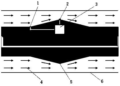
[0015] Such as figure 1 As shown, the measuring device of the present invention includes an airflow variable speed body 5 and a differential pressure gauge 3. The airflow variable speed body 5 is a handle-shaped entity with connecting screw holes at both ends and a protrusion in the middle. The differential pressure gauge 3, the first pressure-taking hole 1 of the differential pressure gauge 3 communicates with the large-diameter airflow channel in the front section of the airflow speed change body 5, and the second pressure-taking hole 2 of the differential pressure gauge 3 communicates with the small-diameter airflow in the middle section of the airflow speed change body 5 aisle.

[0016] The state of use of the measuring device of the present invention is:

[0017] Such as figure 1 As shown, the airflow speed change body 5 is respectively connected with...


PUM


Abstract

The invention discloses a hole bottom gas content measuring device and method. The hole bottom gas content measuring device comprises a gas flow speed changing unit (5) and a differential pressure gauge (3), wherein the inside of the gas flow speed changing unit (5) is provided with the differential pressure gauge (3) with a data storage function, a first pressure measuring hole (1) of the differential pressure gauge (3) is communicated with the front section of the gas flow speed changing unit (5), and a second pressure measuring hole (2) of the differential pressure gauge (3) is communicatedwith the middle section of the gas flow speed changing unit (5). The hole bottom gas content measuring method comprises the steps of 1, measuring a pressure different delta P through the hole bottomgas content measuring device; 2, computing the density of flows at every pressure measuring hole, and according to the sectional area of every pressure measuring hole, computing the emission rate of gas at the front end of a measuring point; 3, according to the relation of gas desorption to time, deducing coal bed original gas content. The hole bottom gas content measuring device and method can solve the problems of desorption time defining difficulty and gas desorption loss of coal samples exposed in air in existing drilling hole sampling technology; meanwhile, the h hole bottom gas content measuring device and method is simple in drilling tool structure and simple in measuring method.

Description

technical field [0001] The invention belongs to gas content measuring technology, in particular to a method for directly and quickly measuring coal seam gas content while drilling in the drilling process. Background technique [0002] Measuring the gas content of coal seams is very important for preventing and controlling gas outbursts. At present, the determination of coal seam gas content is mainly based on the direct measurement method based on borehole sampling. Therefore, the evaluation of gas pressure and content has become a key technology for mining gas-containing coal. However, the biggest disadvantage of drilling sampling technology is that gas-containing coal samples will be exposed to the air, resulting in a certain amount of gas loss and other issues, resulting in the inability to accurately measure the gas content of coal seams, resulting in large deviations in the test results of gas parameters and misjudgment of coal seams Highlight serious issues such as th...

Claims


Application Information

Patent Timeline
Patent Type & Authority Applications(China)
IPC IPC(8): G01N7/14
CPCG01N7/14
Inventor 罗永江王法凯梁运培胡千庭何将福
Owner CHONGQING UNIV
Learn More