Speed-control switch with function of continuously adjusting speed

A speed control switch and speed technology, applied in the field of speed control switches, can solve the problems of inability to achieve continuous speed control, low reliability of contact switches, easy contact wear, etc., and achieve simple structure and assembly, easy disassembly and assembly. The effect of post-maintenance and reliability improvement

Pending Publication Date: 2018-11-27
WUXI CITY LINGHONG ELECTRIC
View PDF5 Cites 0 Cited by
  • Summary
  • Abstract
  • Description
  • Claims
  • Application Information

AI Technical Summary

Problems solved by technology

[0002] In electric tools, speed control switches are widely used, such as hand-held electric drills, electric screw drills, etc. In order to easily adjust the speed and steering of electric tools, a speed control switch is often added to electric tools. However, there are certain shortcomings in the existing speed control switch. The switch part of the existing switch adopts a contact switch. Under normal circumstances, the switch is disconnected, and the push rod switch is pressed to close. The reliability of the contact switch is not high. Contacts are easy to wear and tear, resulting in poor contact; in addition, the speed regulation part adopts resistance step-by-step speed regulation, and several discontinuous speed sections are obtained through different resistance voltage divisions, which cannot realize continuous speed control

Method used


Image

  • Speed-control switch with function of continuously adjusting speed
  • Speed-control switch with function of continuously adjusting speed
  • Speed-control switch with function of continuously adjusting speed

Examples


Embodiment Construction

[0026] The present invention will be further described below in conjunction with the accompanying drawings.

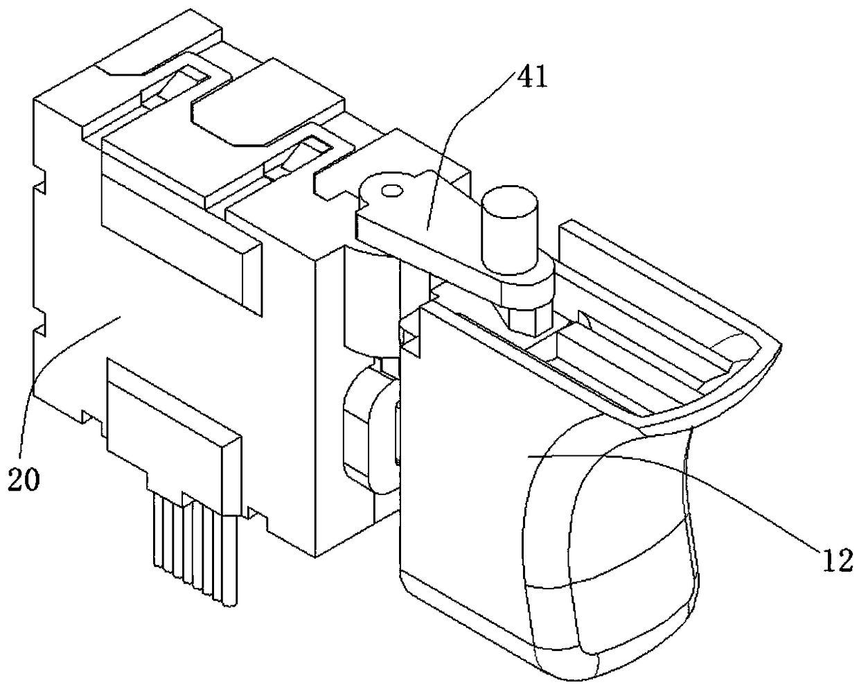
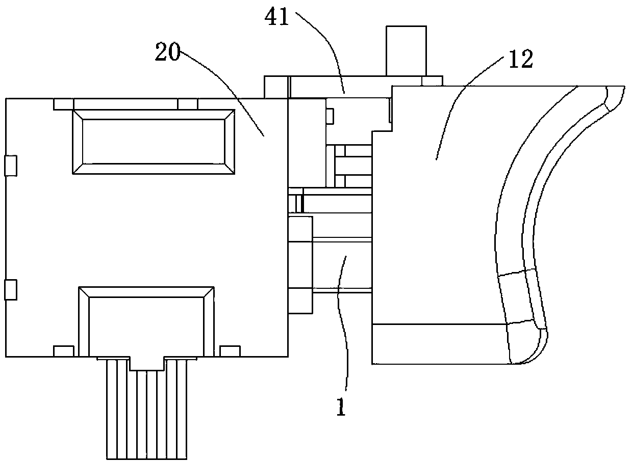
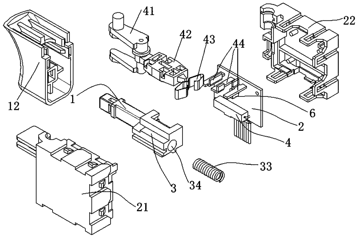
[0027] as attached figure 1 to attach Figure 7 As shown, a speed control switch with continuously adjustable speed includes a housing 20 and a circuit board 2 arranged inside the housing 20, the housing 20 is an inner cavity structure, and is on the same side of the circuit board 2 A push rod 1, a speed regulating slider 3, a reed switch 4 and a Hall sensor 6 are provided, the reed switch 4 is a normally closed reed switch, and the reed switch 4 and the Hall sensor 6 are respectively connected to Circuit board 2 is electrically connected, as attached Figure 11 As shown, the push rod 1 slides elastically and is installed on the housing 20. The end of the push rod inside the housing is provided with a speed regulating slider 3, and the movement outside the housing is provided with a push cap 12. The end of the speed regulating slider 3 away from the push rod 1 is co...


PUM


Abstract

The invention discloses a speed-control switch with function of continuously adjusting speed. The speed-control switch comprises a shell, and a circuit board, a push rod, a speed adjustment sliding block, a dry reed tube and a Hall sensor which are arranged in the shell, wherein the dry reed tube and the Hall sensor are separately and electrically connected with the circuit board; the push rod makes elastic sliding and passes through the shell; the speed adjustment sliding block is arranged at the end, positioned in the shell, of the push rod; the speed adjustment sliding block is arranged atone side of the circuit board in a way of clearance sliding; the speed adjustment sliding block comprises a first magnetic field and a second magnetic field; the dry reed tube is positioned in the first magnetic field, and the Hall sensor is arranged in the second magnetic field; the speed adjustment sliding block makes sliding motion relative to the circuit board; a reed in the dry reed tube is connected or disconnected by sensing the intensity of the first magnetic field; the Hall sensor outputs corresponding Hall voltage by sensing the intensity of the second magnetic field. The normal useof the switch can be effectively guaranteed, contact wear and failure can be prevented, and the speed can be continuously adjusted.

Description

technical field [0001] The invention belongs to the field of speed regulation switches, in particular to a speed regulation switch with continuously adjustable speed. Background technique [0002] In electric tools, speed control switches are widely used, such as hand-held electric drills, electric screw drills, etc. In order to easily adjust the speed and steering of electric tools, a speed control switch is often added to electric tools. However, there are certain shortcomings in the existing speed control switch. The switch part of the existing switch adopts a contact switch. Under normal circumstances, the switch is disconnected, and the push rod switch is pressed to close. The reliability of the contact switch is not high. The contacts are easy to wear and tear, resulting in poor contact; in addition, the speed regulation part adopts resistance step-by-step speed regulation, and several discontinuous speed sections are obtained through different resistance voltage divis...

Claims


Application Information

Patent Timeline
Patent Type & Authority Applications(China)
IPC IPC(8): H01H9/06H01H36/00H03K17/90
CPCH03K17/90H01H9/06H01H36/00
Inventor 张丽刚
Owner WUXI CITY LINGHONG ELECTRIC
Why Eureka
Try Eureka