A kind of optimization design method of ppm structure of high-band space traveling wave tube

An optimized design, traveling wave tube technology, applied in the direction of time-of-flight electron tubes, discharge tubes, electrical components, etc., can solve the problems of large volume of the focusing system, not too many magnetic sheets should be pasted, asymmetrical magnetic rings, etc., to achieve magnetic field Improved symmetry, improved magnetic field asymmetry, and reduced electron beam fluctuations

Active Publication Date: 2020-03-27
UNIV OF ELECTRONICS SCI & TECH OF CHINA
View PDF6 Cites 0 Cited by
  • Summary
  • Abstract
  • Description
  • Claims
  • Application Information

AI Technical Summary

Problems solved by technology

[0003] In the PPM structure, the circular magnetic rings and pole shoes are arranged alternately. The circular magnetic rings are installed on the tube shaft by dividing the magnetic rings into two halves during the assembly of the PPM structure, but this is easy to appear during the assembly process. Assembly error, resulting in asymmetrical magnetic ring
The asymmetry of the assembly of the magnetic ring may cause the magnetic field of the magnetic system to be wrong and cause electrons to be intercepted in the slow wave structure
[0004] At present, there are two ways to adjust the magnetic field asymmetry caused by subsequent assembly: one is to adjust the magnetic system by rotating the magnetic ring without moving the tube; the other is to paste a permanent magnetic sheet or a soft magnetic sheet on the outer surface of the magnetic system to adjust the magnetic field Asymmetry, but this method should not paste too many magnetic sheets, otherwise the entire focusing system will be too large, and may even defocus after a period of time

Method used


Image

  • A kind of optimization design method of ppm structure of high-band space traveling wave tube
  • A kind of optimization design method of ppm structure of high-band space traveling wave tube
  • A kind of optimization design method of ppm structure of high-band space traveling wave tube

Examples


Embodiment Construction

[0024] Taking the 10-period PPM structure with a period of 4mm as an example, the technical solution of the present invention will be further described in detail below.

[0025] (1) Use the Microwave Tube Set Simulator (MTSS) developed by UESTC to simulate the PPM structure and the PPM structure with magnetic ring offset to obtain its magnetic field distribution;

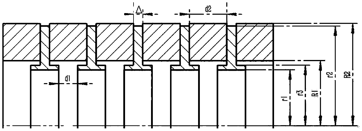
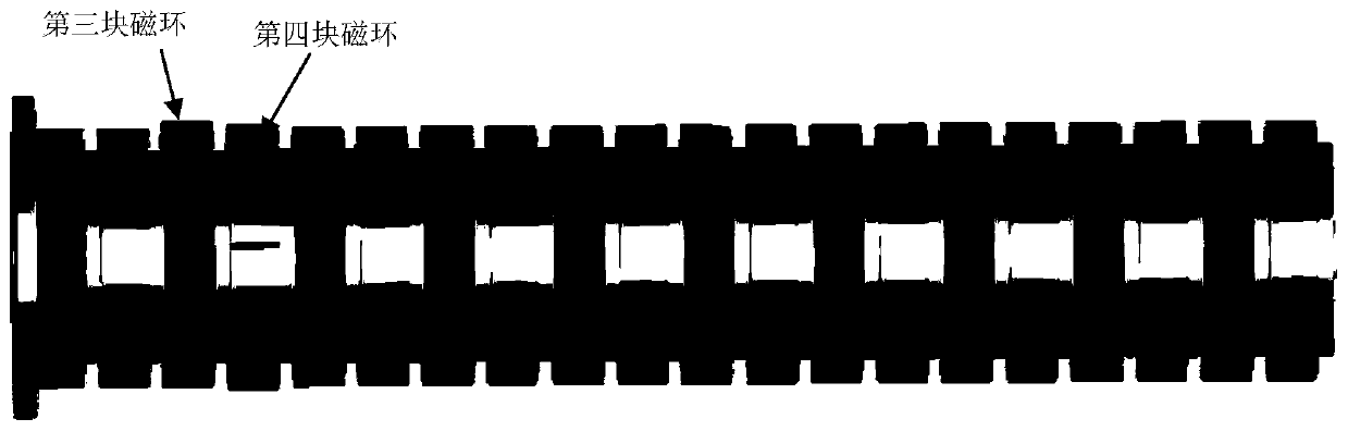
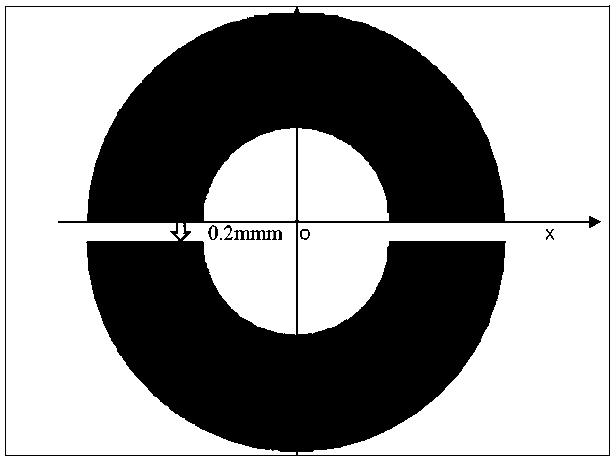
[0026] The PPM structure adopted by the embodiment, such as figure 1 As shown, the circular magnetic rings and pole pieces are arranged alternately, and the material of the magnetic rings is SmCo 28 , The pole shoe material is pure iron _1008. The PPM structure of magnetic ring offset, such as figure 2 As shown, the lower half of the third magnetic ring is offset to the negative direction of the y-axis by 0.2mm, such as image 3 As shown, the upper half of the fourth magnetic ring is offset by 0.1mm to the positive direction of the y-axis, and the offset of the lower half is offset to the negative direction of t...


PUM


Abstract

The invention belongs to the technical field of microwave vacuum electronic devices, and relates to a PPM structure optimization design method of a high-band space traveling wave tube. The present invention presupposes that the offset of the magnetic ring is within the range of 0.2mm, uses the magnetic field simulation software to simulate the PPM pole shoe structure of the magnetic ring offset, and reduces the magnetic field when the magnetic ring is asymmetrical by reducing the inner diameter of the pole shoe Symmetry, improving the asymmetry of the magnetic field caused by the asymmetry of the assembly of the magnetic ring, thereby greatly improving the flow rate of the electron beam. After optimization, the asymmetry of the magnetic field is significantly reduced, and the fluctuation of the electron beam becomes smaller. Compared with the prior art, the present invention proposes a pretreatment idea, optimizes the PPM structure during design to reduce the asymmetry of the magnetic field caused by the asymmetry of the magnetic ring caused by assembly, improves the flow rate of the electron injection, and reduces the design cost of the traveling wave tube. It is conducive to the development of traveling wave tubes to high-wave bands.

Description

technical field [0001] The invention belongs to the technical field of microwave vacuum electronic devices, and relates to a PPM structure optimization design method of a high-band space traveling wave tube. Background technique [0002] Space traveling wave tube is an important core device of national defense equipment such as radar, satellite, and electronic countermeasures. With the rapid development of the national defense industry, the space traveling wave tube is also developing towards the high-band, but the electron optical system is a major technical difficulty of the high-band traveling wave tube. After the wave band of the space traveling wave tube increases, the size of the helix becomes very small , the electron beam channel is very thin, and the interaction part must have a long length, which puts forward high requirements for the focusing system. The PPM structure in the high-wave band is small in size, difficult to process and assemble, and the small asymmet...

Claims


Application Information

Patent Timeline
Patent Type & Authority Patents(China)
IPC IPC(8): H01J9/42H01J23/087
CPCH01J9/42H01J23/0873
Inventor 胡权班雪萍胡玉禄朱小芳杨中海李斌
Owner UNIV OF ELECTRONICS SCI & TECH OF CHINA
Why Eureka
Try Eureka