

A kind of AC and DC universal motor
A common AC and DC, optical axis technology, applied in the direction of electrical components, electromechanical devices, electric components, etc., can solve the problems of non-universal use, limited use of motors, etc., and achieve the effects of high work efficiency, simple structure, and wide application range.
- Summary
- Abstract
- Description
- Claims
- Application Information
AI Technical Summary
Problems solved by technology
Method used
Image

Examples
Embodiment 1
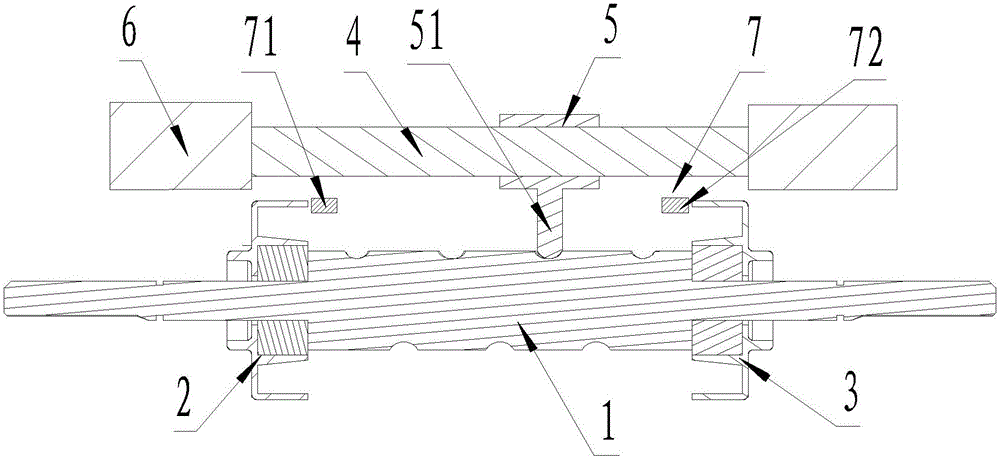
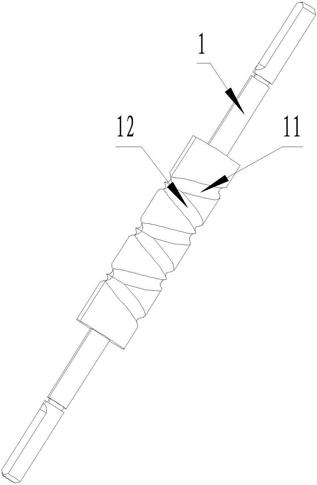
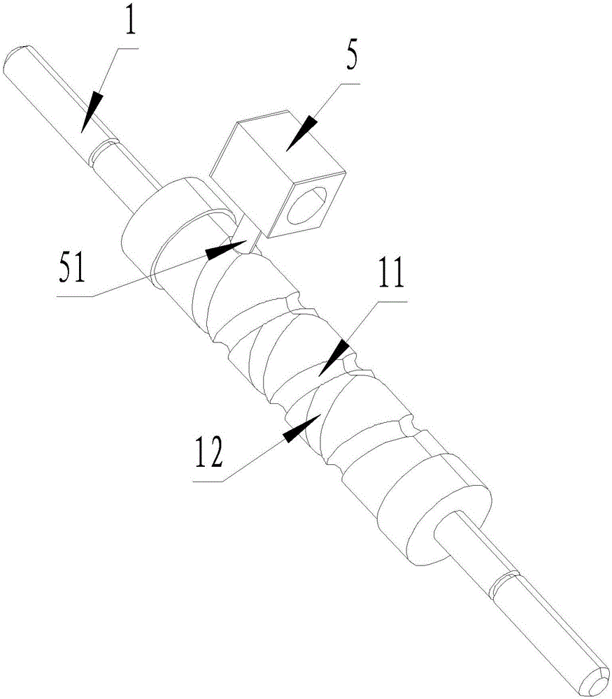
[0039] Embodiment one: if figure 1 , figure 2 , image 3 , Figure 4 and Figure 5 As shown, the present invention is an AC / DC universal motor, comprising a rotating shaft 1, a left supporting frame 2, a right supporting frame 3, an optical axis 4, a sliding magnetic pole 5, at least one fixed magnetic pole 6 and several position detection devices 7, the rotating shaft 1 has two The ends are respectively supported on the bearings of the left supporting frame 2 and the right supporting frame 3, and the optical shaft 4 is arranged side by side outside the rotating shaft 1, the sliding magnetic pole 5 is installed on the optical axis 4 and can move along the optical axis 4, the outer surface of the rotating shaft 1 There are double threaded grooves on the top, which are left-handed threaded grooves 11 and right-handed threaded grooves 12 respectively. Left-handed threaded grooves 11 and right-handed threaded grooves 12 are respectively connected at the head end and tail to fo...
Embodiment 2
[0047] Embodiment two: if Figure 7 As shown, the difference from Embodiment 1 is that the fixed magnetic pole 6 includes a left fixed magnetic pole 61, and the left fixed magnetic pole 61 includes a left iron core 611 and a left coil winding 612 wound on the left iron core 611, and the left iron core 611 is set At one end of the optical axis 4 , the sliding pole 5 includes a sleeve 52 , a transmission rod 51 protruding from the sleeve 52 and a sliding coil winding 53 wound on the sleeve 52 .
[0048] Such as Figure 8 and Figure 9 As shown, the position detection device 7 is a magnetic induction switch, including a left magnetic induction switch 71 and a right magnetic induction switch 72, the external power input is connected to the left coil winding 612 through a left current direction switching device 81, and the left magnetic induction switch 71 and the right magnetic induction switch 72 detect Slide the position signal of magnetic pole 5 and send the position signal t...
Embodiment 3
[0051] Embodiment three: as Figure 10 As shown, the difference from Embodiment 1 is that the fixed magnetic pole 6 includes a left fixed magnetic pole 61 and a right fixed magnetic pole 62, and the left fixed magnetic pole 61 includes a left iron core 611 and a left coil winding 612 wound on the left iron core 611, The right fixed magnetic pole 62 includes a right iron core 621 and a right coil winding 622 wound on the right iron core 621. The left iron core 611 and the right iron core 621 are respectively set on the two ends of the optical axis 4. The sliding magnetic pole 5 includes a sleeve 52, The transmission rod 51 protruding from the sleeve 52, which is a permanent magnet.
[0052] Such as Figure 11 and Figure 12 As shown, the position detection device 7 is a magnetic induction switch, including a left magnetic induction switch 71 and a right magnetic induction switch 72, the external DC power input is connected with the left coil winding 612 through a left current...
PUM
 Abstract
Description
Claims
Application Information