Glue diluting machine for manufacturing electronic components

A technology of electronic components and glue, which is applied in the field of diluters, can solve the problems of manpower and time, uneven mixing, etc.

Inactive Publication Date: 2018-11-30
廖淼帆
View PDF8 Cites 1 Cited by
  • Summary
  • Abstract
  • Description
  • Claims
  • Application Information

AI Technical Summary

Problems solved by technology

[0003] In order to overcome the shortcomings of manual stirring that consumes a lot of manpower and time, and the stirring is uneven, the technical problem to be solved is: to provide a method for manufacturing electronic components that does not require manual dilution, saves time and effort, and stirs evenly. glue thinner

Method used


Image

  • Glue diluting machine for manufacturing electronic components
  • Glue diluting machine for manufacturing electronic components
  • Glue diluting machine for manufacturing electronic components

Examples


Embodiment 1

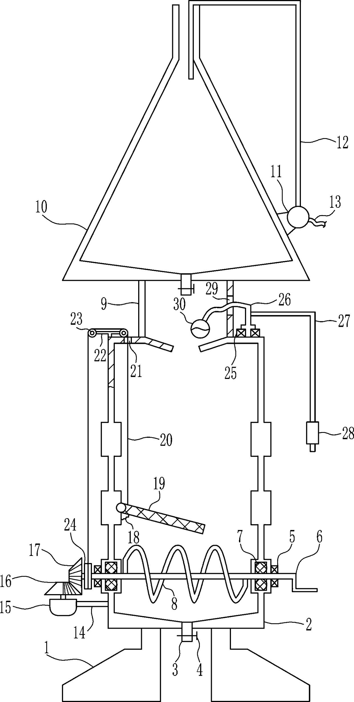
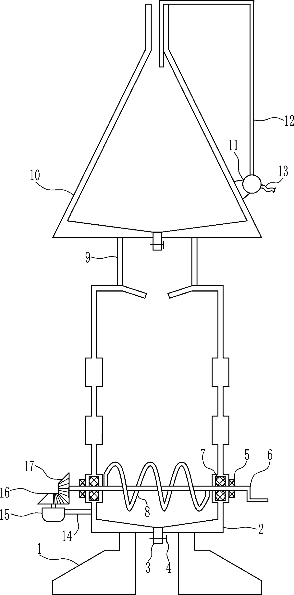
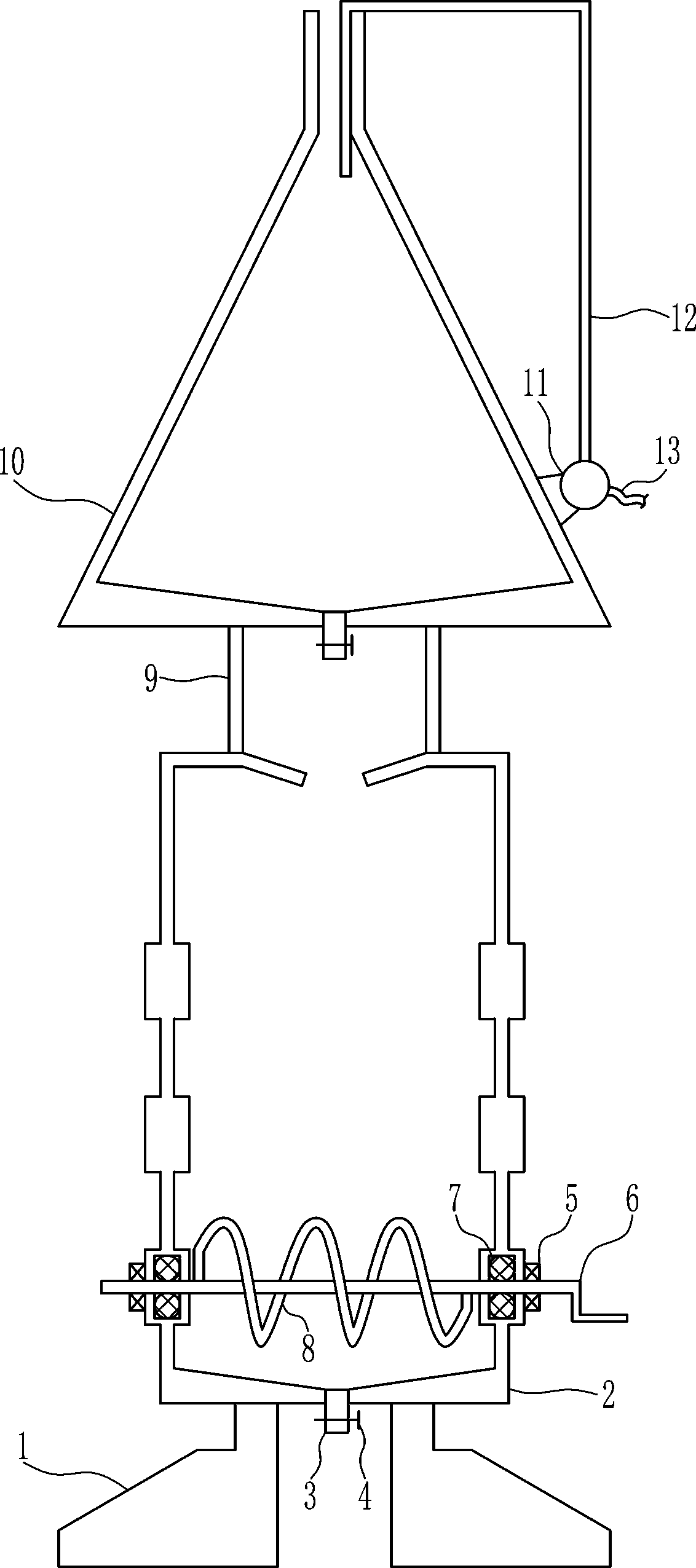
[0023] A kind of glue diluting machine for the manufacture of electronic components, such as Figure 1-5 As shown, it includes support seat 1, dilution box 2, discharge pipe 3, valve 4, first bearing seat 5, first rotating rod 6, sealing ring 7, screw rod 8, support rod 9, box body 10, pumping Liquid pump 11, feed pipe 12 and hose 13, the left and right sides of the lower side of the dilution tank 2 are equipped with support bases 1, the lower parts of the left and right walls of the dilution tank 2 are equipped with the first bearing seat 5, and the left and right sides of the first bearing seat 5 are installed. The interference connection of a bearing seat 5 is connected with the first rotating rod 6, and the left and right parts of the first rotating rod 6 are covered with sealing rings 7. Connected with a screw rod 8, the screw rod 8 is located in the dilution box 2, the left and right sides of the upper side of the dilution box 2 are fixedly connected with a support rod 9...

Embodiment 2

[0025] A kind of glue diluting machine for the manufacture of electronic components, such as Figure 1-5 As shown, it includes support seat 1, dilution box 2, discharge pipe 3, valve 4, first bearing seat 5, first rotating rod 6, sealing ring 7, screw rod 8, support rod 9, box body 10, pumping Liquid pump 11, feed pipe 12 and hose 13, the left and right sides of the lower side of the dilution tank 2 are equipped with support bases 1, the lower parts of the left and right walls of the dilution tank 2 are equipped with the first bearing seat 5, and the left and right sides of the first bearing seat 5 are installed. The interference connection of a bearing seat 5 is connected with the first rotating rod 6, and the left and right parts of the first rotating rod 6 are covered with sealing rings 7. Connected with a screw rod 8, the screw rod 8 is located in the dilution box 2, the left and right sides of the upper side of the dilution box 2 are fixedly connected with a support rod 9...

Embodiment 3

[0028]A kind of glue diluting machine for the manufacture of electronic components, such as Figure 1-5 As shown, it includes support seat 1, dilution box 2, discharge pipe 3, valve 4, first bearing seat 5, first rotating rod 6, sealing ring 7, screw rod 8, support rod 9, box body 10, pumping Liquid pump 11, feed pipe 12 and hose 13, the left and right sides of the lower side of the dilution tank 2 are equipped with support bases 1, the lower parts of the left and right walls of the dilution tank 2 are equipped with the first bearing seat 5, and the left and right sides of the first bearing seat 5 are installed. The interference connection of a bearing seat 5 is connected with the first rotating rod 6, and the left and right parts of the first rotating rod 6 are covered with sealing rings 7. Connected with a screw rod 8, the screw rod 8 is located in the dilution box 2, the left and right sides of the upper side of the dilution box 2 are fixedly connected with a support rod 9,...


PUM


Abstract

The invention relates to a diluting machine, in particular to a glue diluting machine for manufacturing electronic components. The technical problems to be solved is that the glue diluting machine does not need manual dilution, time and labor are saved and the stirring is uniform. The glue diluting machine comprises supporting bases, a diluting box, a discharging pipe, a valve, first bearing seats, a first rotating rod, a sealing ring, a screw rod, a supporting rod, a box body, a liquid pumping pump and the like; the left part and the right part of the lower side of the diluting box are respectively provided with the supporting bases, and the lower parts of the outer sides of the left wall and the right wall of the diluting box are respectively provided with the first bearing seats, and the first rotating rod is in interference connection with the first bearing seats on the left side and the right side. The screw rod is driven by a servo motor to rotate, the glue and the diluent in thediluting box can be automatically stirred, so that the glue and the diluent can be uniformly stirred, a swinging net plate swings up and down, the diluting liquid in the diluting box can be made moreuniformly, and therefore manpower and time are saved.

Description

technical field [0001] The invention relates to a diluting machine, in particular to a glue diluting machine for manufacturing electronic components. Background technique [0002] The manufacture of electronic components requires a lot of glue, and the glue needs to be diluted before use. At present, the glue and the thinner are usually poured into the container together, and then the glue in the container is manually mixed with a stirring rod. The agent is stirred, and in order to stir evenly, people need to stir the stirring rod for a long time, and like this, people's arm is easy to be sore, needs to expend more manpower and time. Contents of the invention [0003] In order to overcome the shortcomings of manual stirring that consumes a lot of manpower and time, and the stirring is uneven, the technical problem to be solved is: to provide a method for manufacturing electronic components that does not require manual dilution, saves time and effort, and stirs evenly. Glu...

Claims


Application Information

Patent Timeline
Patent Type & Authority Applications(China)
IPC IPC(8): B01F13/10B01F15/00
CPCB01F33/821B01F35/00B01F2035/351B01F2035/352B01F35/3202B01F35/3204B01F35/43B01F2101/36
Inventor 廖淼帆
Owner 廖淼帆
Why Eureka
Try Eureka