Precision pneumatic clamp for machining

A pneumatic fixture and machining technology, applied in the direction of manufacturing tools, metal processing equipment, metal processing machinery parts, etc., can solve the problems of unstable product size, low clamping efficiency, uneven clamping force, etc., to achieve clamping High efficiency, stable product size, and convenient use

Inactive Publication Date: 2018-11-30
深圳市晶铸科技有限公司
View PDF8 Cites 3 Cited by
  • Summary
  • Abstract
  • Description
  • Claims
  • Application Information

AI Technical Summary

Problems solved by technology

[0003] The invention provides a precision pneumatic clamp for machining, which aims to solve the problems of low clamping efficiency, uneven clamping force, easy deformation during product processing and unstable product size in the existing clamps

Method used


Image

  • Precision pneumatic clamp for machining
  • Precision pneumatic clamp for machining
  • Precision pneumatic clamp for machining

Examples


Embodiment 1

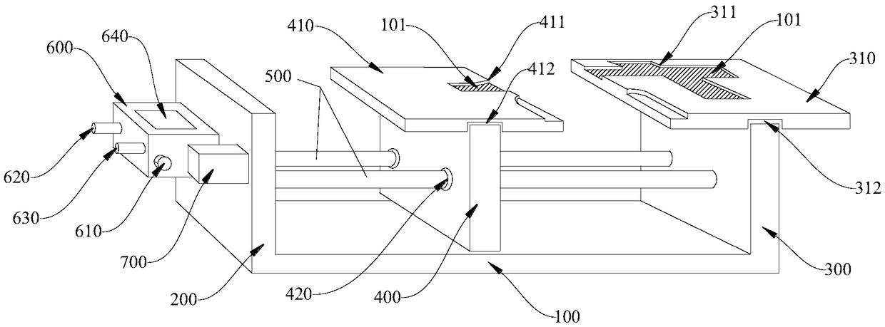
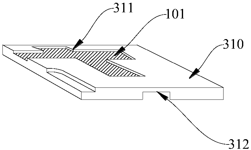
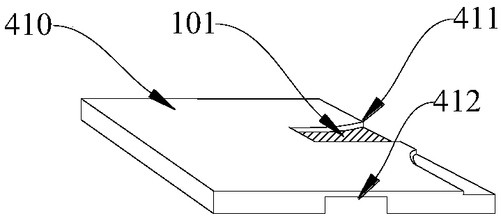
[0027] see Figure 1-Figure 5 , in an embodiment of the present invention, a precision pneumatic fixture for machining, including a base 100, a first fixed side plate 200, a second fixed side plate 300, a sliding plate 400, a fixed clamp block 310, and a sliding cover plate 410 , 2 guide rails 500, a cylinder 600, a manual valve 610 and an air flow regulating valve 700, the first fixed side plate 200 and the second fixed side plate 300 are installed on the left and right ends of the base 100 respectively, the cylinder 600 and The air flow regulating valve 700 is installed on the outer side wall of the first fixed side plate 200, the fixed splint 310 is installed on the upper end of the second fixed side plate 300, and one end of the two guide rails 500 is inserted through the first A fixed side plate 200 is connected to the cylinder 600, and the other end is inserted through the second fixed side plate 300, and the sliding plate 400 is installed on the two guide rails 500 betw...


PUM


Abstract

The invention is suitable for the technical field of machines, and provides a precision pneumatic clamp for machining. The precision pneumatic clamp comprises a base, a first fixed side plate, a second fixed side plate, a sliding plate, a fixed clamping block, a sliding cover plate, two guide rails, an air cylinder, a manual valve and an airflow adjusting valve; the first fixed side plate and thesecond fixed side plate are installed on the left and right ends of the base, the air cylinder and the airflow adjusting valve are installed on the outer side wall of the first fixed side plate, the fixed clamping plate is installed at the upper end of the second fixed side plate, one ends of the two guide rails are inserted into the first fixed side plate to be connected with the air cylinder ina penetrating manner, and the other ends of the two guide rails are inserted into the second fixed side plate; and the sliding plate is installed on the two guide rails and are located between the first fixed side plate and the second fixed side plate, the sliding cover plate is installed at the upper end of the sliding plate, the fixed clamping plate is flush with the sliding cover plate, the manual valve is installed on the air cylinder, and the air cylinder is connected with the airflow adjusting valve and the manual valve. The clamp is convenient to use and high in clamping efficiency, theclamping force can be evenly adjusted, and the product cannot deform and is stable in size.

Description

technical field [0001] The invention belongs to the technical field of machinery, and in particular relates to a precision pneumatic clamp for machining. Background technique [0002] Many industrial products need to be positioned and then processed during the production process, and various fixtures need to be used. For different types of products, the profiles and positioning holes of the products are different, and various fixtures need to be used. The stability of the fixture itself, as well as the reliability of the cooperation between the fixture and the product workpiece, have a great impact on the final machining accuracy of the product. It has an important influence, so different product workpieces and even different clamping positions have different requirements on the fixture. The existing traditional fixture adopts manual thread clamping, which has low clamping efficiency for special-shaped products to be processed, high clamping difficulty, uneven clamping forc...

Claims


Application Information

Patent Timeline
Patent Type & Authority Applications(China)
IPC IPC(8): B23Q3/08
CPCB23Q3/08
Inventor 吴振宇
Owner 深圳市晶铸科技有限公司
Why Eureka
Try Eureka