Automatic stacking fixture

A stacking and automatic technology, applied in the field of automatic palletizing jigs, can solve the problems of high labor intensity and low efficiency, and achieve the effect of reducing labor intensity, reducing production costs, and ensuring positional accuracy

Pending Publication Date: 2021-01-22
北京京城智通机器人科技有限公司
View PDF0 Cites 0 Cited by
  • Summary
  • Abstract
  • Description
  • Claims
  • Application Information

AI Technical Summary

Problems solved by technology

[0003] In order to solve the problems of high labor intensity and low efficiency in the process of manual handling and transfer of bent pieces in the prior art, the present invention provides an automatic palletizing jig

Method used


Image

  • Automatic stacking fixture
  • Automatic stacking fixture
  • Automatic stacking fixture

Examples


Embodiment 1

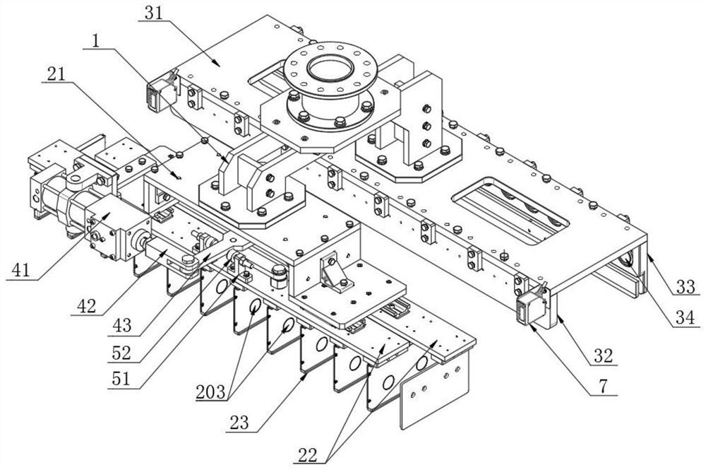
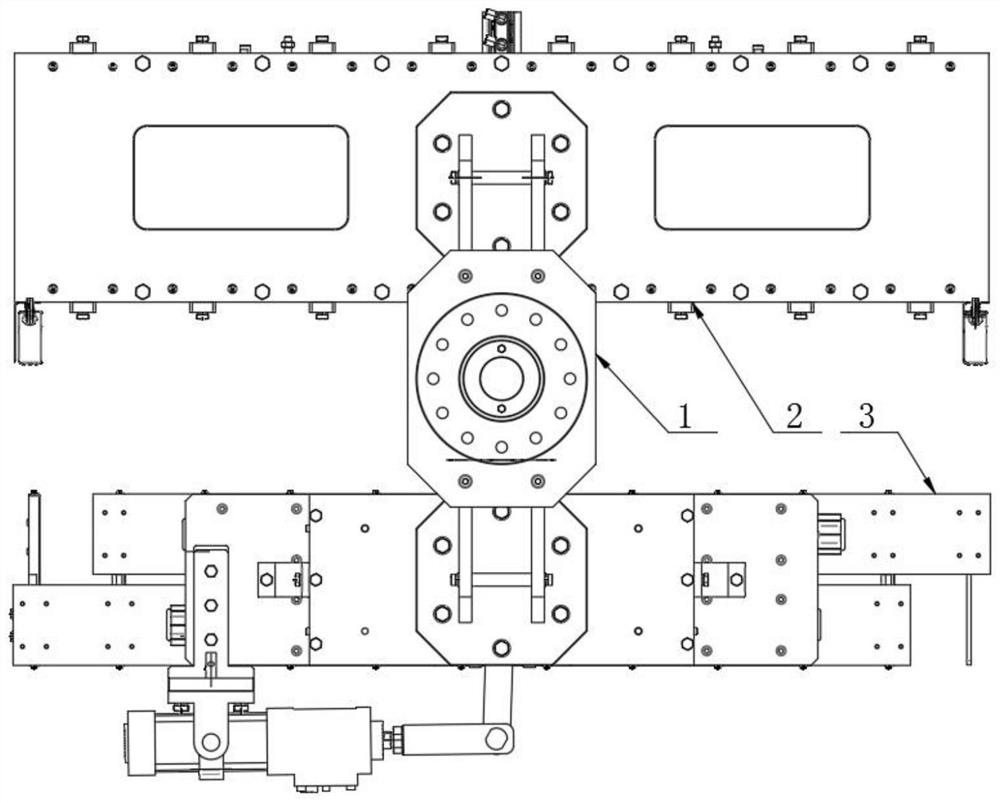
[0030] refer to figure 1 , figure 2 , image 3 and Figure 4, the automatic palletizing jig of the present invention comprises a robot and a connecting plate 1, and the robot is connected to the middle part of the connecting plate 1; one end of the connecting plate 1 is provided with a coding mechanism 2, and the other end is provided with a song unloading mechanism 3; The mechanism 3 includes a base 21 and two mutually parallel slide plates 22 slidably connected to the bottom of the base. The bottom of the slide plates is evenly provided with splints 23 parallel to each other. The distance between adjacent splints matches the width of the curved block; the base 21 is provided with a drive The power mechanism that slide plate 22 moves; Described code song mechanism 2 comprises base plate 31 and the side plate that is arranged on both sides of base plate, the distance between two side plates is matched with the length of curved block, and any side plate is provided with for ...

Embodiment 2

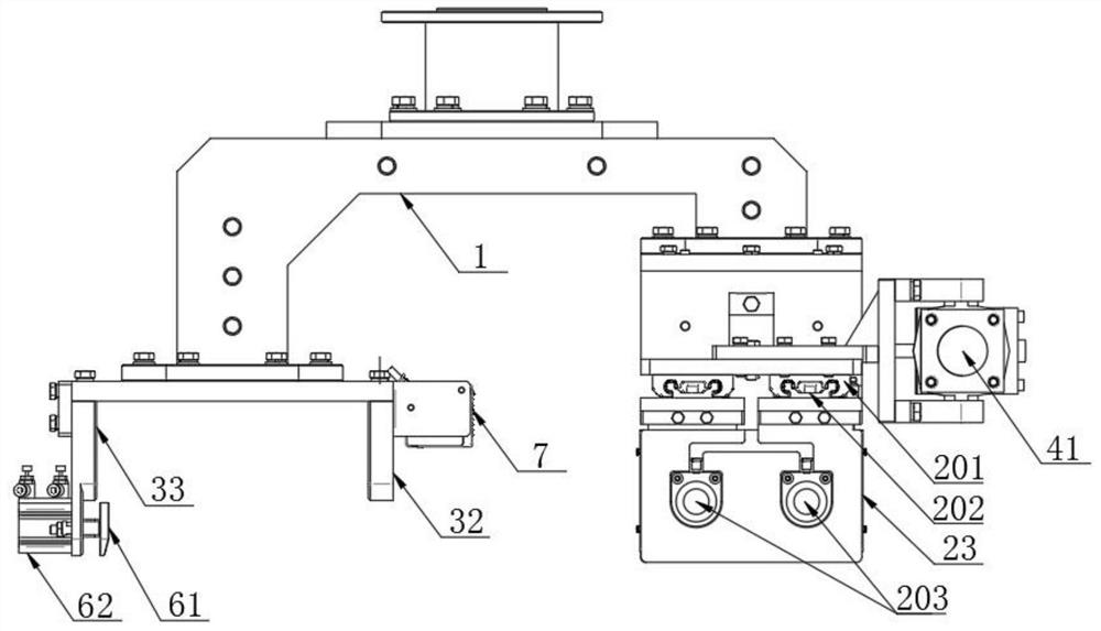
[0040] refer to figure 1 and image 3 , on the basis of Embodiment 1, this embodiment is provided with a damping mechanism for buffering the fall of the curved block on the side plate; the side plate includes a long plate 33 and a short plate 32, and the long plate 33 matches the height of the curved block, Short plate 32 height is less than long plate 33 heights; Described damping mechanism comprises the push plate 61 that is arranged on long plate 33 bottoms and is parallel with short plate 32 and drives the second cylinder 62 that pushes plate telescopic toward short plate; The fixing of second cylinder The end is fixedly connected with the long plate 33, and the movable end of the second cylinder is connected with the push plate 61.

[0041] Working principle: When the unloading mechanism transports the curved block to the pallet, the first floating clamping mechanism releases the curved block, and the curved block naturally falls to the lower pallet under the action of g...

Embodiment 3

[0044] The difference between this embodiment and Embodiment 1 is that the structure of the second floating clamping mechanism 203 is different. The second floating clamping mechanism 203 of this embodiment is an airbag, and the airbag is connected to the compressor through the air pipe. The airbag has elasticity, and when the curved piece needs to be clamped, air is ventilated into the airbag, and the airbag bulges to clamp the curved piece; the airbag meets the clamping of the curved piece in this scheme, and it is flexibly connected with the curved piece to protect the curved piece.


PUM


Abstract

The invention discloses an automatic stacking fixture. The automatic stacking fixture comprises a robot and a connecting plate. One end of the connecting plate is provided with a koji stacking mechanism, and the other end is provided with a koji unloading mechanism. The koji stacking mechanism comprises a base and two parallel sliding plates connected to the bottom of the base slidably, wherein parallel clamping plates are evenly arranged at the bottoms of the sliding plates, the distance between every two adjacent clamping plates is matched with the width of koji blocks, and a power mechanismfor driving the sliding plates to move is arranged on the base. The koji unloading mechanism comprises a bottom plate and side plates arranged on the two sides of the bottom plate, wherein the distance between the two side plates is matched with the length of the koji blocks, and a first floating clamping mechanism used for clamping the koji blocks is arranged on any side plate. According to theautomatic stacking fixture, the traditional process of manually transferring the koji blocks is replaced, the automation degree is high, the labor intensity is reduced, the production cost is reduced,and the production efficiency is improved; and moreover, the automatic stacking fixture is a composite fixture, can finish the transfer of koji blocks in two procedures on the same device at the sametime, and is high in universality.

Description

technical field [0001] The invention relates to the technical field of brewing, in particular to an automatic palletizing jig. Background technique [0002] During the brewing process, after the grains are steamed, it is necessary to add koji medicine to the grains during the drying process to facilitate the subsequent fermentation of the grains. Koji medicine is made by a koji making machine, and the koji pieces produced by the koji making machine need to be fermented in a koji room. The existing process of making koji (that is, the process of fermenting and storing koji pieces in the room after they come out of the koji making machine) is very backward in automation, and the related operations are mainly carried out manually: the koji pieces produced by the koji making machine are manually Take it to the corresponding shelf, and then transport the shelf to the koji room for fermentation. After the koji pieces are fermented, move the koji pieces on the koji racks to pallet...

Claims


Application Information

Patent Timeline
Patent Type & Authority Applications(China)
IPC IPC(8): B65G61/00B65G47/90
CPCB65G47/904B65G47/907B65G61/00
Inventor 孙云权刘少力黄兴博陈姗
Owner 北京京城智通机器人科技有限公司
Why Eureka
Try Eureka