Steel ball cleaning equipment for hardware
A technology for cleaning equipment and steel balls, applied to metal processing equipment, cleaning methods using tools, cleaning methods and appliances, etc., which can solve the problems of high labor consumption, easy falling out, and long time spent
- Summary
- Abstract
- Description
- Claims
- Application Information
AI Technical Summary
Problems solved by technology
Method used
Image

Examples
Embodiment 1
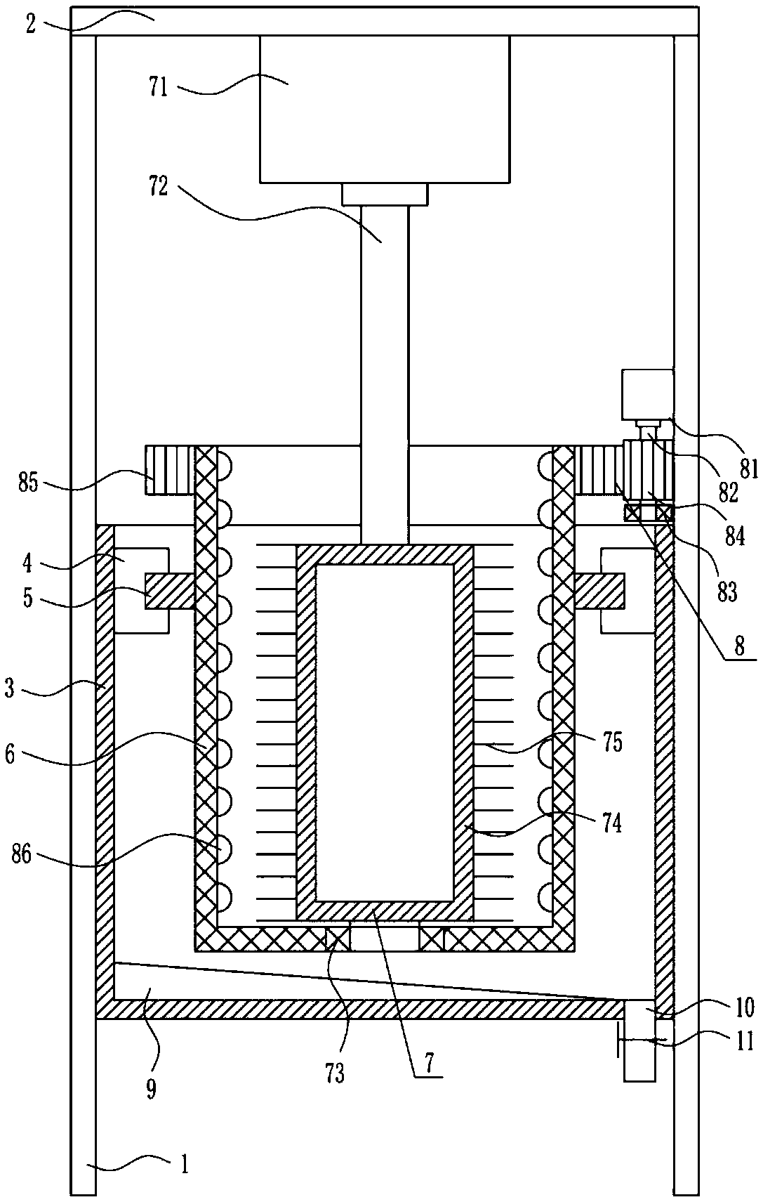
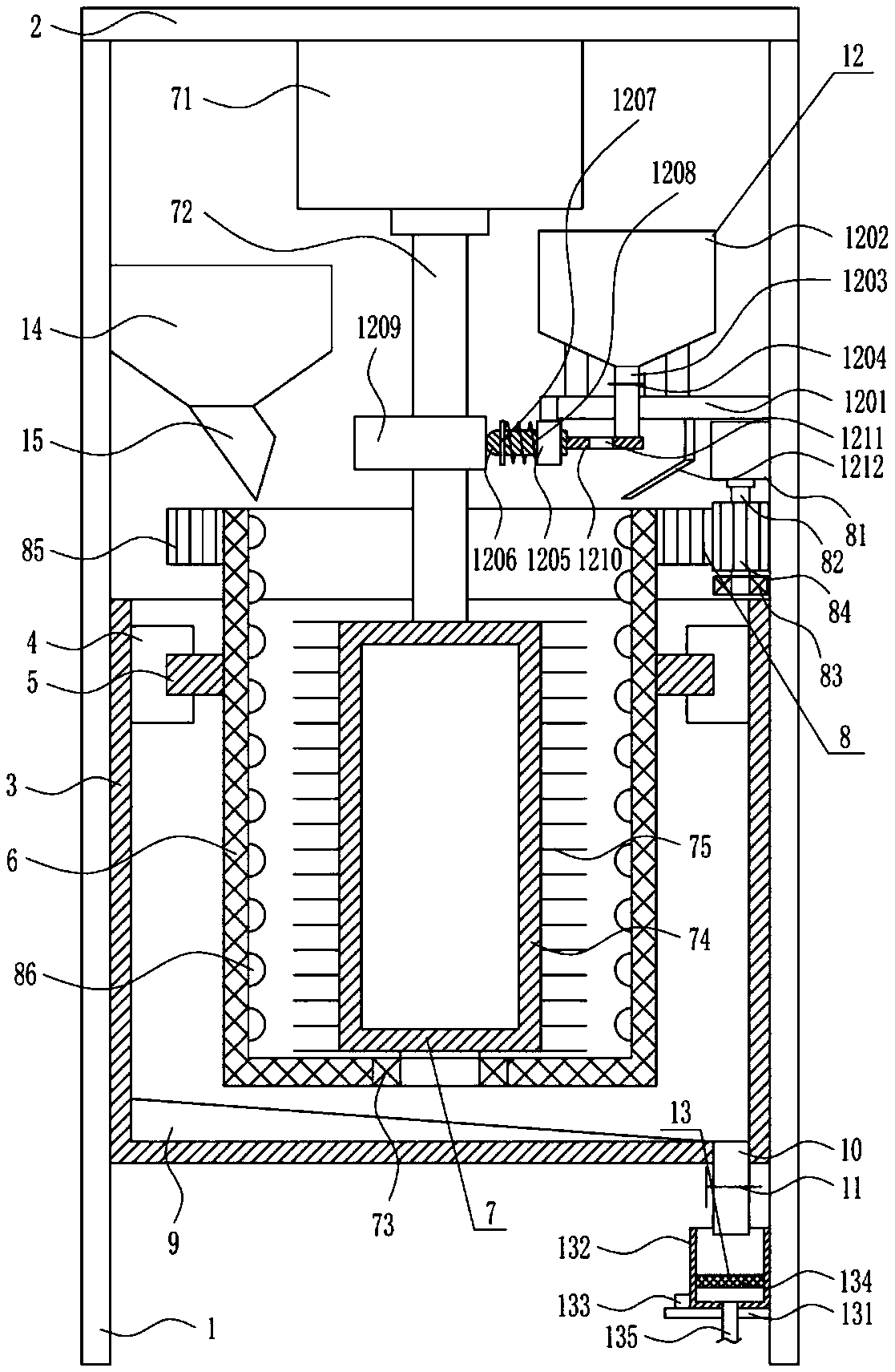
[0023] A steel ball cleaning equipment for hardware, such as Figure 1-2 As shown, it includes a leg 1, a top plate 2, a treatment box 3, an annular slide rail 4, a slider 5, a cage 6, a cleaning mechanism 7, a friction mechanism 8, a wedge block 9, a first material guide pipe 10 and a first Valve 11, the top of the left and right side legs 1 is provided with a top plate 2, the bottom between the left and right side legs 1 is connected with a treatment box 3, the top of the inner wall of the treatment box 3 is provided with a ring slide rail 4, and the ring slide rail 4 is provided with A plurality of sliders 5 are connected with a net cage 6 between the sliders 5, a cleaning mechanism 7 is installed on the bottom of the top plate 2, a friction mechanism 8 is installed on the legs 1, and a wedge block 9 is arranged at the bottom of the processing box 3. 3. The right side of the bottom is connected with a first material guide pipe 10, and a first valve 11 is provided on the fir...
Embodiment 2
[0025] A steel ball cleaning equipment for hardware, such as Figure 1-2As shown, it includes a leg 1, a top plate 2, a treatment box 3, an annular slide rail 4, a slider 5, a cage 6, a cleaning mechanism 7, a friction mechanism 8, a wedge block 9, a first material guide pipe 10 and a first Valve 11, the top of the left and right side legs 1 is provided with a top plate 2, the bottom between the left and right side legs 1 is connected with a treatment box 3, the top of the inner wall of the treatment box 3 is provided with a ring slide rail 4, and the ring slide rail 4 is provided with A plurality of sliders 5 are connected with a net cage 6 between the sliders 5, a cleaning mechanism 7 is installed on the bottom of the top plate 2, a friction mechanism 8 is installed on the legs 1, and a wedge block 9 is arranged at the bottom of the processing box 3. 3. The right side of the bottom is connected with a first material guide pipe 10, and a first valve 11 is provided on the firs...
Embodiment 3
[0028] A steel ball cleaning equipment for hardware, such as Figure 1-2 As shown, it includes a leg 1, a top plate 2, a treatment box 3, an annular slide rail 4, a slider 5, a cage 6, a cleaning mechanism 7, a friction mechanism 8, a wedge block 9, a first material guide pipe 10 and a first Valve 11, the top of the left and right side legs 1 is provided with a top plate 2, the bottom between the left and right side legs 1 is connected with a treatment box 3, the top of the inner wall of the treatment box 3 is provided with a ring slide rail 4, and the ring slide rail 4 is provided with A plurality of sliders 5 are connected with a net cage 6 between the sliders 5, a cleaning mechanism 7 is installed on the bottom of the top plate 2, a friction mechanism 8 is installed on the legs 1, and a wedge block 9 is arranged at the bottom of the processing box 3. 3. The right side of the bottom is connected with a first material guide pipe 10, and a first valve 11 is provided on the fir...
PUM
 Abstract
Description
Claims
Application Information
 - R&D Engineer
- R&D Manager
- IP Professional
- Industry Leading Data Capabilities
- Powerful AI technology
- Patent DNA Extraction
Browse by: Latest US Patents, China's latest patents, Technical Efficacy Thesaurus, Application Domain, Technology Topic.
© 2024 PatSnap. All rights reserved.Legal|Privacy policy|Modern Slavery Act Transparency Statement|Sitemap