A Gradual Compensation Method for Robot Positioning Error

A technology of robot positioning and compensation method, which is applied in the direction of manipulators, program-controlled manipulators, manufacturing tools, etc., can solve the problems of large estimation errors, achieve the effects of improving accuracy, improving absolute positioning accuracy, and correctly estimating parameter errors

Active Publication Date: 2021-09-07
CHENGDU AIRCRAFT INDUSTRY GROUP
View PDF7 Cites 0 Cited by
  • Summary
  • Abstract
  • Description
  • Claims
  • Application Information

AI Technical Summary

Problems solved by technology

The calculation process of this method is simple, and there is no need to establish a complex error model, but when the attitude of the point to be compensated changes greatly, the estimation error using this method may be large

Method used


Image

  • A Gradual Compensation Method for Robot Positioning Error
  • A Gradual Compensation Method for Robot Positioning Error
  • A Gradual Compensation Method for Robot Positioning Error

Examples


Embodiment 1

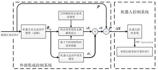
[0034] The present invention is realized through the following technical solutions, as figure 1 As shown, a robot positioning error classification compensation method specifically includes the following steps:

[0035]Step S1: Randomly select the theoretical pose P of m sampling points in the area to be compensated s , using a laser tracker to measure the actual arrival pose P of the robot m , to get the end pose error ΔP of the robot before compensation m =P m -P s ;

[0036] Step S2: Establish the kinematic relationship between the connecting rods of the robot to obtain the kinematics model of the robot; establish the kinematics error model of the robot;

[0037] Step S3: Solve the kinematic error model in step S2, obtain the optimal solution of each kinematic parameter error and the corrected kinematic model, and calculate the end pose P of the robot under the corrected kinematic model k ;

[0038] Step S4: The end pose P of the robot under the corrected kinematic mo...

Embodiment 2

[0050] A hierarchical compensation method for robot positioning errors, which analyzes the distribution of robot positioning errors and the mechanism of error sources, and divides the main influencing factors of positioning errors into two types: geometric parameter errors and non-geometric parameter errors. Aiming at the error factors of geometric parameters, a coupling parameter error model is proposed which comprehensively considers the establishment error of the robot frame coordinate system and the error of geometric parameters. Aiming at non-geometric parameter error factors, a residual error model based on spatial similarity is proposed. By studying the hierarchical compensation control mechanism, the robot's hierarchical error compensation based on coupling parameter identification and spatial similarity is realized, and the absolute positioning accuracy of the robot is further improved.

[0051] Specifically include the following steps:

[0052] Step S1: Randomly sel...

Embodiment 3

[0066] Such as figure 1 As shown, a robot positioning error classification compensation method specifically includes the following steps:

[0067] Step S1: Randomly select the theoretical pose P of m sampling points in the area to be compensated s , using a laser tracker to measure the actual arrival pose P of the robot m , to get the end pose error ΔP of the robot before compensation m =P m -P s .

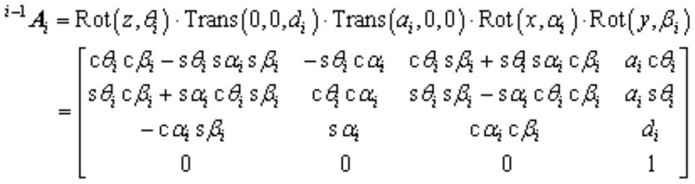
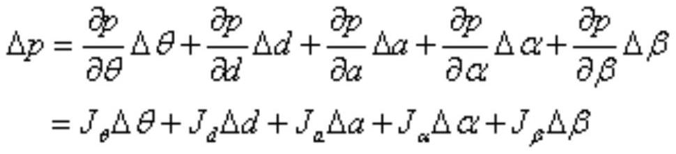
[0068] Step S2: Use the D-H model to establish the kinematic relationship between the connecting rods of the robot to obtain the kinematics model of the robot; according to the theoretical pose P of random sampling points given in step S1 s and the actual pose P measured by the laser tracker m , to establish the robot kinematics error model, the model is established as follows:

[0069] Use the D-H model to establish the kinematic relationship between the connecting rods of the robot. In order to avoid the singularity that occurs when two adjacent axes are parallel or nearl...


PUM


Abstract

The invention discloses a hierarchical compensation method for positioning error of a robot, which comprises the following steps: calculating the position and posture error of the front end before compensation; establishing a kinematics model and a kinematics error model; calculating the optimal solution of each kinematics parameter error and the corrected kinematics model and the corrected kinematics model under the terminal pose; calculate the compensation amount input after positioning error compensation; calculate the actual arrival pose, and obtain the residual error after parameter calibration; establish a residual error estimation model to compensate the desired target point; Predict the positioning error; predict the residual error of the expected target point; calculate the input compensation amount; calculate the actual arrival pose of the end, and the compensation is completed. The invention can effectively improve the industrial absolute positioning accuracy; adopting the residual error model based on the spatial similarity can reflect the anisotropy of the positioning error in space.

Description

technical field [0001] The invention relates to the technical field of automatic drilling and riveting, in particular to a method for grading and compensating robot positioning errors. Background technique [0002] The development of emerging robot technology enables robots to be used as a high-quality and high-efficiency platform, together with subsystems such as end effectors, flexible tooling, and detection and perception, to form various robotic flexible automation systems. With the support of emerging technologies, industrial robots are gradually expanding towards high-precision fields, and work tasks are developing towards high-efficiency and precision operations. Therefore, in order to achieve the higher quality, higher efficiency, and higher flexibility manufacturing and assembly technical requirements of the aviation industry, the improvement of the absolute positioning accuracy of industrial robots has become a technical problem that needs to be solved urgently. I...

Claims


Application Information

Patent Timeline
Patent Type & Authority Patents(China)
IPC IPC(8): B25J9/16
CPCB25J9/1692
Inventor 石章虎田威孟华林郑法颖曾德标张霖何晓煦
Owner CHENGDU AIRCRAFT INDUSTRY GROUP
Why Eureka
Try Eureka