
Rail vehicle lifting method, coupler mounting seat for implementation of rail vehicle lifting method and rail vehicle

A coupler mounting seat and rail vehicle technology, applied in the field of rail vehicles, can solve the problems of easily damaged vehicle structure, no reliable fixed point, displacement of four lifting points, etc., and achieve increased vehicle cost, simple and convenient operation, and stable lifting Effect

Active Publication Date: 2018-11-30
CRRC QINGDAO SIFANG CO LTD
View PDF6 Cites 0 Cited by
  • Summary
  • Abstract
  • Description
  • Claims
  • Application Information

AI Technical Summary

Problems solved by technology

At present, when the vehicle is loaded, the lifting of the vehicle body structure is fixed through the holes set on the side of the vehicle. During the lifting process, the four lifting points may be displaced, resulting in failure to lift the vehicle.
There is no reliable fixing point when the vehicle is fixed on the transport vehicle, and it is basically fixed on some functional parts (such as empty spring observation hole, hanging seat, shock absorber seat, etc.) and it is easy to damage the vehicle structure

Method used


Image

  • Rail vehicle lifting method, coupler mounting seat for implementation of rail vehicle lifting method and rail vehicle
  • Rail vehicle lifting method, coupler mounting seat for implementation of rail vehicle lifting method and rail vehicle

Examples


Embodiment 1

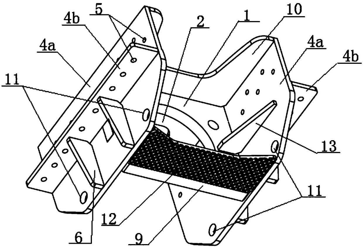
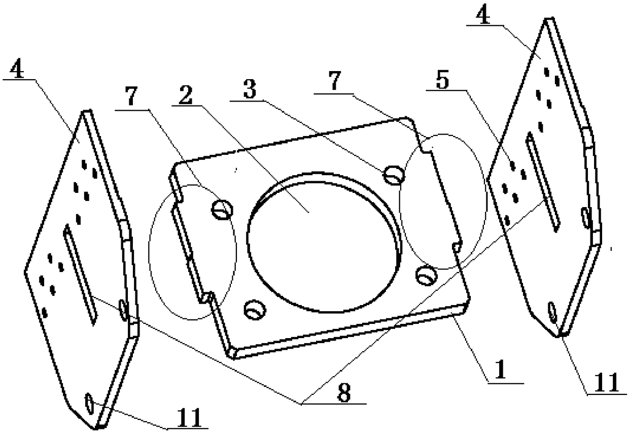
[0027] Such as figure 1 and figure 2 As shown, a coupler mounting seat provided by the present invention is fixedly installed on the draw beam (not shown in the figure) at the front part of the vehicle body underframe, and the coupler mounting seat is installed between the two draw beams. A coupler mounting seat is respectively installed at the front and rear ends of the car body.

[0028] The coupler mounting seat includes a coupler mounting plate 1, the setting direction of the coupler mounting plate 1 is perpendicular to the coupler, and the center of the coupler mounting plate 1 has an opening 2 for passing through the coupler (not shown in the figure). Four installation holes 3 are arranged around the opening 2 in the center, and the installation holes 3 are fixedly connected with the coupler by bolts.

[0029] A vertical plate 4 is respectively installed on both sides of the coupler mounting plate 1, and the two vertical plates 4 are perpendicular to the coupler mount...

Embodiment 2

[0043] This embodiment provides a method for lifting a rail vehicle, which is used to hoist the vehicle body to a required position when the vehicle body needs to be transported or transferred to another work station, such as a vehicle or ship for transporting the vehicle body, Or wait on the station that needs to be overhauled.

[0044] When lifting the car, the bearing part (not shown in the figure) used for lifting the car is leaned against and supported from below on the lifting floor 9 of the coupler mounting seat as described in Embodiment 1, and the couplers at the front and rear ends of the car body are installed. Each bearing is installed under the seat, and the bearing is connected with the lifting device. The lifting device can be a crane for hoisting. The two sides of each bearing are respectively connected with the crane through the straps. Lift and lift the car body as a whole to the required position.

[0045] After hoisting the car body to the transport vehicl...

Embodiment 3

[0048] This embodiment provides a rail vehicle, including a bogie, a car body, etc. The car body is composed of sides, end walls, roof and an underframe, and traction beams are installed at the front and rear ends of the underframe. The longitudinal direction of the body is provided with two parallel, as described in the first embodiment, the coupler mount is installed between the two draw beams, and the two sides of the coupler mount are respectively fixedly connected with the draw beams on both sides by rivets.


PUM


Abstract

The invention relates to a rail vehicle lifting method, a coupler mounting seat for implementation of the rail vehicle lifting method and a rail vehicle. A bearing part is abutted against a coupler mounting seat from below, and a lifting device is connected with the bearing part and used for lifting up a vehicle body. The coupler mounting seat comprises a coupler mounting plate which is provided with an opening allowing penetration of a coupler, two vertical plates for fixed connection with the vehicle body are mounted on two sides of the coupler mounting plate respectively, a lifting bottom plate for lifting and supporting is arranged between the two vertical plates below the coupler mounting plate, and two sides of the lifting bottom plate are fixedly connected with the two vertical plates. The coupler mounting seat in a special structure serves as a vehicle lifting supporting point to support the whole vehicle body, the vehicle body can be integrally lifted through lifting of the coupler mounting seat, convenience in vehicle disassembly, mounting and transporting is achieved, simplicity and convenience in operation are achieved, and stability in lifting is guaranteed.

Description

technical field [0001] The invention belongs to the technical field of rail vehicle manufacturing, and relates to a method for lifting a rail vehicle, a coupler mounting seat for realizing the lifting method, and a rail vehicle equipped with the coupler mounting seat. Background technique [0002] With the development of the rail transit industry, more and more vehicles are manufactured and repaired by vehicle suppliers, and more vehicles are transported by road. At present, when the vehicle is loaded, the lifting of the vehicle body structure is fixed through the holes provided on the side of the vehicle. During the lifting process, the four lifting points may be displaced, resulting in failure to lift the vehicle. There is no reliable fixing point when the vehicle is fixed on the transport vehicle, and it is basically fixed on some functional parts (such as empty spring observation hole, hanging seat, shock absorber seat, etc.), which is easy to damage the vehicle structur...

Claims


Application Information

Patent Timeline
IPC IPC(8): B61K5/02B61K11/00
CPCB61K5/02B61K11/00
Inventor 郑伟张泽云闫立志田洪雷梁君海
Owner CRRC QINGDAO SIFANG CO LTD
Learn More