Rope end safety locking mechanism of elevator compensation system

A technology for elevator compensation and safety locking, applied in elevators, transportation and packaging, etc., can solve the problems of easy breakage, poor connection safety, and inability to ensure the stability of the safety rope connection, and achieves enhanced stability, guaranteed use safety, and connection. tight effect

Inactive Publication Date: 2018-11-30
TIANJIN XINBAOLONG ELEVATOR GRP
View PDF0 Cites 0 Cited by
  • Summary
  • Abstract
  • Description
  • Claims
  • Application Information

AI Technical Summary

Problems solved by technology

[0002] The elevator compensation system is a device that balances the weight between the elevator car and the counterweight when the elevator is running by connecting both ends of the safety rope to the elevator car and the counterweight. When there is a large drop from the elevator car, the weight of the safety rope is used to offset the weight of the elevator car or the traction wire rope at one end of the counterweight, so as to ensure the stable operation of the elevator. Usually, a hook is used to connect the safety rope, and the connection safety is poor.
[0003] However, if the ordinary hook is used to connect the safety rope, the hook that bears the weight of the safety rope is easily broken for a long time, and the connection stability of the safety rope cannot be guaranteed, and the hook is used to hang the chain opening at the end of the safety rope, and the safety rope shakes and the chain rubs against the hook. It is easy to break and cannot provide effective protection for the safety rope to prevent the safety rope from breaking and loosening

Method used


Image

  • Rope end safety locking mechanism of elevator compensation system
  • Rope end safety locking mechanism of elevator compensation system
  • Rope end safety locking mechanism of elevator compensation system

Examples


Embodiment Construction

[0024] The following will clearly and completely describe the technical solutions in the embodiments of the present invention with reference to the accompanying drawings in the embodiments of the present invention. Obviously, the described embodiments are only some, not all, embodiments of the present invention. Based on the embodiments of the present invention, all other embodiments obtained by persons of ordinary skill in the art without making creative efforts belong to the protection scope of the present invention.

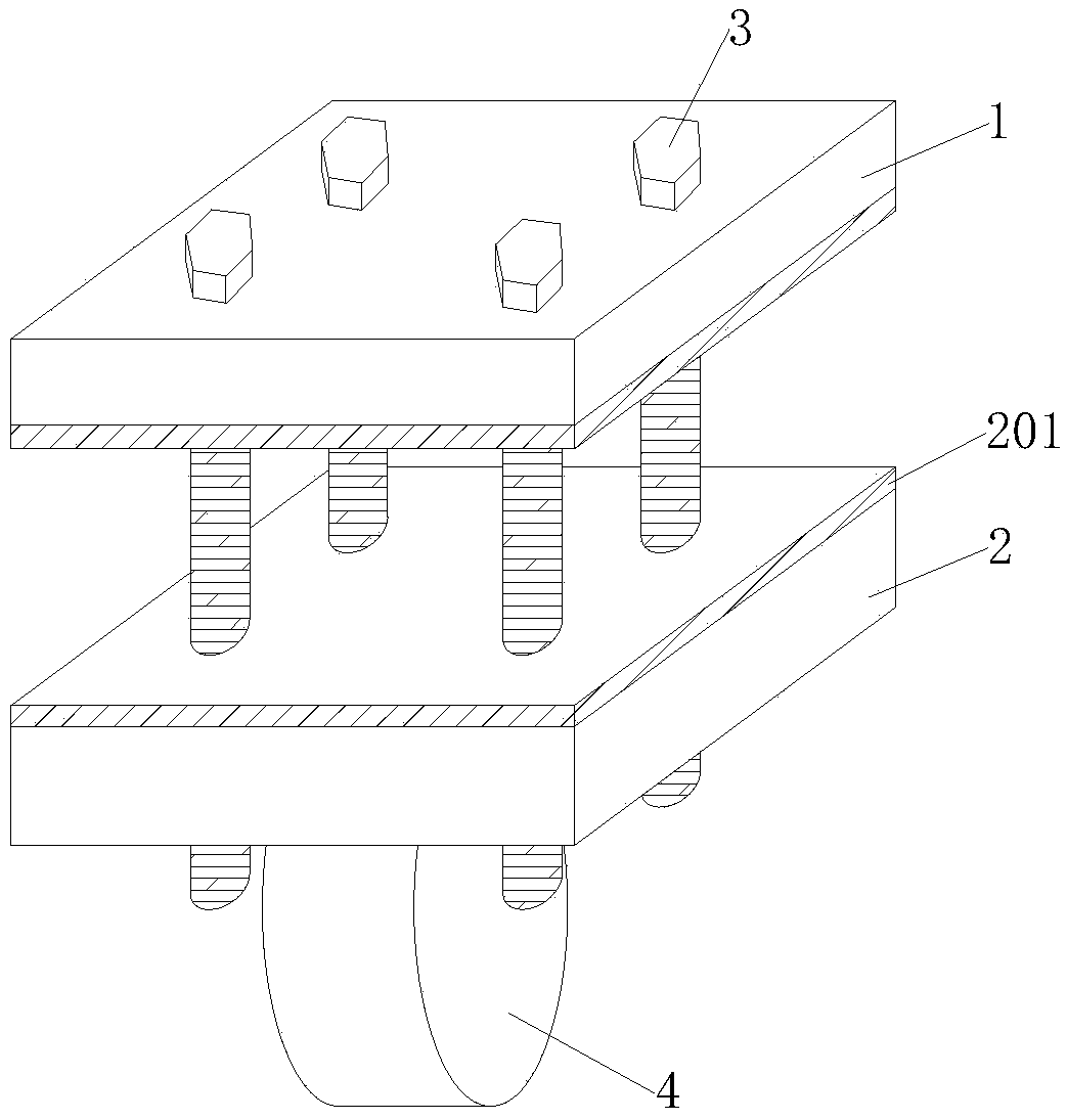
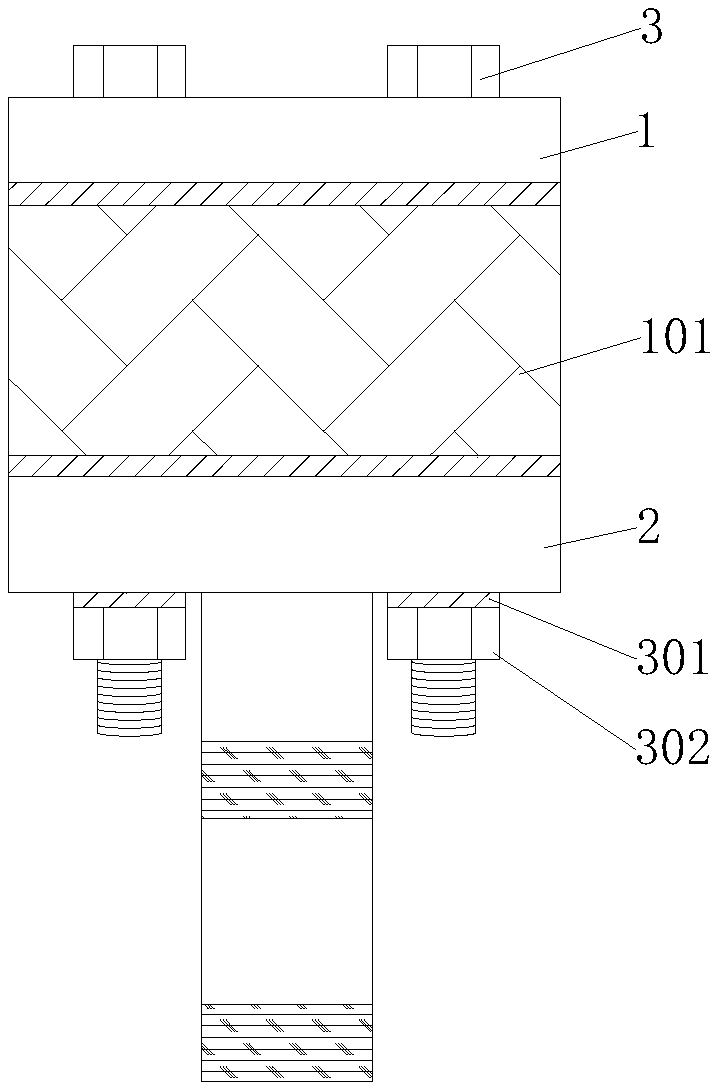
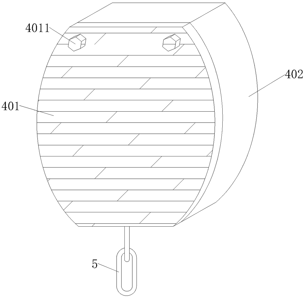
[0025] see Figure 1-4 , the present invention provides a technical solution: a rope end safety locking mechanism for an elevator compensation system, including an upper cover 1, a lower cover 2, a connecting base 4 and a connecting base 4 for connecting the upper cover 1 and the lower cover 2 high-strength bolts 3, the four corners of the upper end surface of the upper cover plate 1 are connected with high-strength bolts 3, the lower end surface of the upper ...


PUM


Abstract

The invention discloses a rope end safety locking mechanism of an elevator compensation system, and belongs to the field of elevator equipment. The technical scheme is characterized in that the mechanism comprises an upper cover plate, a lower cover plate, a connecting base and high-strength bolts used for making the upper cover plate connected with the lower cover plate; the high-strength bolts penetrate through the four corners of the upper end face of the upper cover plate, and the lower end surface of the upper cover plate is fixedly connected with the lower cover plate; a car bottom plateis tightly attached to the gap between the upper cover plate and the lower cover plate; and a rubber pad layer is tightly attached to the upper end face of the lower cover plate. The lower cover plate and the car bottom plate are connected more tightly through the rubber pad layer, and a protection cover plate is used for blocking a front opening of an arc-shaped groove, so that the stability ofconnection between a base station and a compensation chain is enhanced. The compensation chain is fixed through a connection pile, and secondary locking is carried out on the compensation chain through thin bolts, so that the use safety of the compensation chain is guaranteed. The compensation chain is locked through stainless steel buckles, so that the connection stability of the compensation chain is enhanced.

Description

technical field [0001] The invention relates to the field of elevator equipment, in particular to a rope end safety locking mechanism of an elevator compensation system. Background technique [0002] The elevator compensation system is a device that balances the weight between the elevator car and the counterweight when the elevator is running by connecting both ends of the safety rope to the elevator car and the counterweight. When there is a large drop from the elevator car, the weight of the safety rope is used to offset the weight of the elevator car or the traction wire rope at one end of the counterweight, so as to ensure the stable operation of the elevator. Usually, a hook is used to connect the safety rope, and the connection safety is poor. [0003] However, if the ordinary hook is used to connect the safety rope, the hook that bears the weight of the safety rope is easily broken for a long time, and the connection stability of the safety rope cannot be guaranteed,...

Claims


Application Information

Patent Timeline
IPC IPC(8): B66B5/02B66B7/08
CPCB66B5/02B66B7/08
Inventor 曹杰曹嘉鑫
Owner TIANJIN XINBAOLONG ELEVATOR GRP
Why Eureka
Try Eureka