A pipe pile spreader

A technology of pipe piles and spreaders, which is applied in the field of spreaders, can solve the problems of single hoisting methods and lack of protective measures for spreaders, and achieve the effects of avoiding slipping and falling, improving the protection effect, and avoiding manual disassembly

Active Publication Date: 2019-12-13
安徽凯越电力杆塔有限公司
View PDF5 Cites 0 Cited by
  • Summary
  • Abstract
  • Description
  • Claims
  • Application Information

AI Technical Summary

Problems solved by technology

[0003] The current spreader lacks good protection measures when lifting, and most of the hoisting methods can only be hoisted horizontally or vertically alone, and the hoisting method is single

Method used


Image

  • A pipe pile spreader
  • A pipe pile spreader
  • A pipe pile spreader

Examples


Embodiment Construction

[0029] In order to make the technical means, creative features, goals and effects achieved by the present invention easy to understand, the present invention will be further described below in conjunction with specific embodiments.

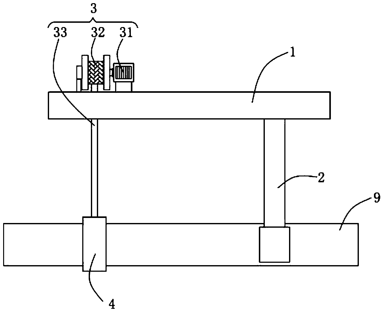
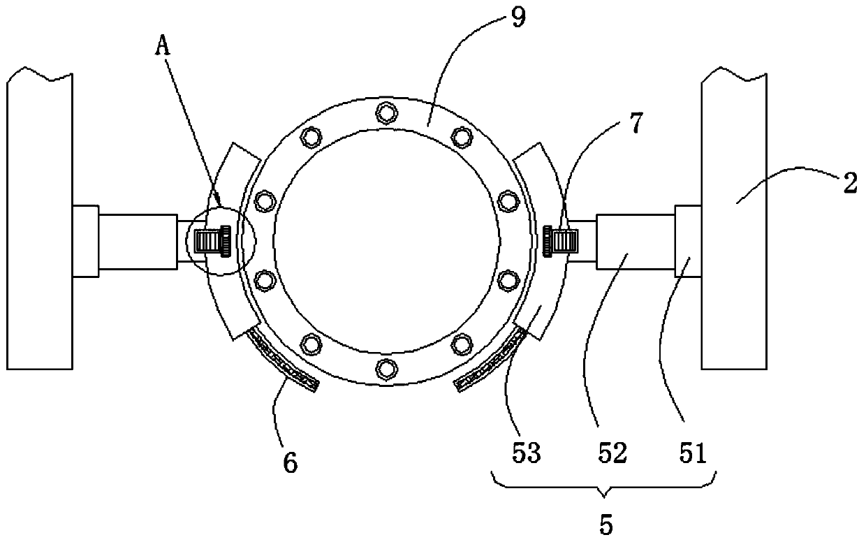
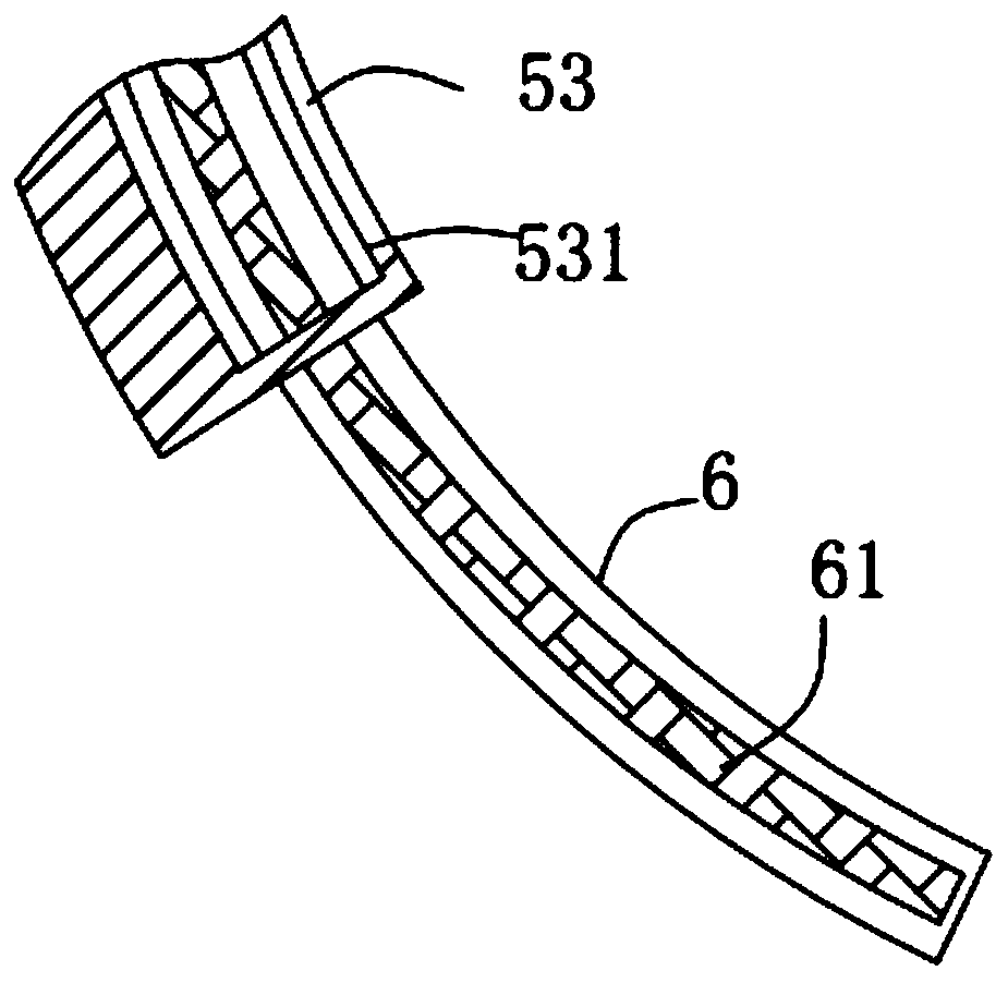
[0030] Such as Figure 1-Figure 5 As shown, a pipe pile spreader according to the present invention includes a traction plate 1, a fixed plate 2, a traction mechanism 3, a first clamping mechanism 4, a second clamping mechanism 5, a protective plate 6, a driving mechanism 7 and Locking mechanism 8; the traction mechanism 3 is provided on the surface of the traction plate 1, and the traction mechanism 3 is fixedly connected to the first clamping mechanism 4, and the first clamping mechanism 4 is used to clamp the pipe pile fixed, the traction mechanism 3 is used to adjust the position of the first clamping mechanism 4; the first clamping mechanism 4 is screwed with the locking mechanism 8, and the locking mechanism 8 is used for The first clamping...


PUM


Abstract

The invention relates to the technical field of sling equipment, in particular to a tubular pile sling. The tubular pile sling comprises a drawing plate, fixing plates, a drawing mechanism, a first clamping mechanism, second clamping mechanisms, protecting plates, driving mechanisms and a locking mechanism. According to the tubular pile sling, the protecting plates can be driven to move outwards through a third rotating motor so that the protecting plates of arc-shaped structures can be placed at the bottom of the tubular pile, and therefore the protecting effect can be further improved, and slipping and falling of the tubular pile are avoided. When the tubular pile needs to be vertically placed, the drawing mechanism can drive the tubular pile to rotate downwards in a tilting mode along an arc, the second clamping mechanisms rotate around a rotating base, the top end of the tubular pile rotates automatically around the second clamping mechanisms, and therefore the tubular pile can bevertically placed, the drawing mechanism can pull and fix the tubular pile, and the tubular pile can be made more stable and safer. When the tubular pile is rotated to be vertical, the locking mechanism can separate the second clamping mechanisms, the drawing mechanism can drive the second clamping mechanisms to break away from the tubular pile, and manual dismantling is avoided.

Description

technical field [0001] The invention relates to the technical field of spreaders, in particular to a spreader for pipe piles. Background technique [0002] Prestressed concrete pipe piles can be divided into post-tensioned prestressed pipe piles and pretensioned prestressed pipe piles; pretensioned prestressed pipe piles are hollow cylinders made by pretensioning prestressing technology and centrifugal forming Slender concrete prefabricated components, mainly composed of cylindrical pile body, end plate and steel ferrule. [0003] The current spreader lacks better protection measures when hoisting, and most of the hoisting methods can only be horizontally hoisted or vertically hoisted separately, and the hoisting method is single. In view of this, the present invention provides a pipe pile spreader, which has the following characteristics: [0004] (1) The pipe pile spreader according to the present invention can respectively clamp and fix the two ends of the pipe pile thr...

Claims


Application Information

Patent Timeline
Patent Type & Authority Patents(China)
IPC IPC(8): B66C1/42B66C1/44
CPCB66C1/42B66C1/44
Inventor 陈伟光
Owner 安徽凯越电力杆塔有限公司
Why Eureka
Try Eureka