Double-hook crane slewing trolley

A technology of cranes and double hooks, applied in the direction of load block, spring mechanism, load hanging components, etc., can solve the problems of inability to rotate, inconvenient use, limited use range, etc., to prolong life, use flexibly, weaken The effect of lateral stress influence

Pending Publication Date: 2018-11-30
德马科起重机械有限公司
View PDF0 Cites 1 Cited by
  • Summary
  • Abstract
  • Description
  • Claims
  • Application Information

AI Technical Summary

Problems solved by technology

[0002] Ordinary cranes run horizontally on the track on the main girder to realize the transfer of goods, but they cannot rotate, which limits the direction of the reel to hang the goods. It is necessary to move the goods first for the hook to hang, which is inconvenient to use. And they are all single hooks, which have light lifting weight and limited application range; therefore, a double-hook crane slewing trolley is required

Method used


Image

  • Double-hook crane slewing trolley
  • Double-hook crane slewing trolley
  • Double-hook crane slewing trolley

Examples


Embodiment 1

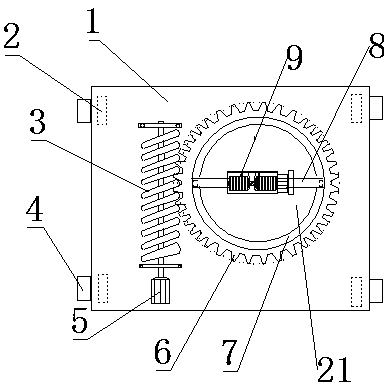
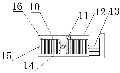
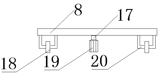
[0015] Such as Figure 1-3 As shown, the purpose of the present invention is achieved in this way: a double-hook crane slewing trolley, which includes a slewing trolley body 1, the four corners of the slewing trolley body 1 are provided with walking wheels 2, and the walking The outer sides of the wheels 2 are provided with elastic buffer pads 4, the left side of the revolving trolley body 1 is provided with a worm 3, one end of the worm 3 is connected with a frequency conversion motor 5, and the right side of the worm 3 is provided There is a turntable 21, the outer side of the turntable 21 is provided with a ring gear 6, the worm 3 is meshed with the ring gear 6, the inner side of the ring gear 6 is provided with a rotating ring 7, and the rotating ring 7 is A support plate 8 is provided, and a lifting mechanism 9 is arranged above the support plate 8, and the lifting mechanism 9 is composed of a reel 16 and a motor 13, and a fixed rod 12 is arranged above the reel 16 , the...

Embodiment 2

[0018] Such as Figure 1-3 As shown, the purpose of the present invention is achieved in this way: a double-hook crane slewing trolley, which includes a slewing trolley body 1, the four corners of the slewing trolley body 1 are provided with walking wheels 2, and the walking The outer sides of the wheels 2 are provided with elastic buffer pads 4, the left side of the revolving trolley body 1 is provided with a worm 3, one end of the worm 3 is connected with a frequency conversion motor 5, and the right side of the worm 3 is provided There is a turntable 21, the outer side of the turntable 21 is provided with a ring gear 6, the worm 3 is meshed with the ring gear 6, the inner side of the ring gear 6 is provided with a rotating ring 7, and the rotating ring 7 is A support plate 8 is provided, and a lifting mechanism 9 is arranged above the support plate 8, and the lifting mechanism 9 is composed of a reel 16 and a motor 13, and a fixed rod 12 is arranged above the reel 16 , the...


PUM


Abstract

The invention relates to a double-hook crane slewing trolley. The double-hook crane slewing trolley comprises a slewing trolley body, wherein the left side of the slewing trolley body is equipped witha worm; one end of the worm is connected with a variable-frequency motor; the right side of the worm is equipped with a rotary table; the outer side of the rotary table is equipped with a gear ring;the inner side of the gear ring is equipped with a rotary ring; a supporting plate is arranged on the rotary ring; a lifting mechanism is arranged above the supporting plate; the lifting mechanism consists of coiling blocks and an electric motor; a fixed rod is arranged above the coiling blocks; the electric motor is arranged at the right sides of the coiling blocks; the left side of the electricmotor is connected with main transmission shafts; left and right coiling blocks are arranged on the main transmission shafts; the middle part below the left supporting plate is connected with a rotaryshaft; and a small motor is connected below the rotary shaft. The double-hook crane slewing trolley has the advantages of being stable and accurate in rotation, safe and reliable, and flexible in use.

Description

technical field [0001] The invention belongs to the technical field of cranes, and in particular relates to a double-hook crane slewing trolley. Background technique [0002] Ordinary cranes run horizontally on the track on the main girder to realize the transfer of goods, but they cannot rotate, which limits the direction of the reel to hang the goods. It is necessary to move the goods first for the hook to hang, which is inconvenient to use. And all are single suspension hook, and its hoisting weight is light, and scope of application is limited; Therefore, need a kind of double suspension hook crane rotary trolley. Contents of the invention [0003] The purpose of the present invention is to overcome the deficiencies of the prior art, and provide a double-hook crane slewing trolley with stable and accurate rotation, safety and reliability, and flexible use. [0004] The object of the present invention is achieved in the following way: a double-hook crane slewing trolle...

Claims


Application Information

Patent Timeline
Patent Type & Authority Applications(China)
IPC IPC(8): B66C11/16B66D1/12B66D1/14
CPCB66C11/16B66D1/12B66D1/14
Inventor 董彦波毛义雪孔纯恒
Owner 德马科起重机械有限公司
Why Eureka
Try Eureka