Wall scraping device for building construction
A technology for building construction and walls, which is applied in construction, building maintenance, building construction, etc. It can solve the problems of not being able to scrape off the wall quickly, the scraping range of the wall is small, and the work efficiency is reduced, so as to achieve an ingenious structure , Improve scraping quality and prolong service life
- Summary
- Abstract
- Description
- Claims
- Application Information
AI Technical Summary
Problems solved by technology
Method used
Image
Examples
Embodiment 1
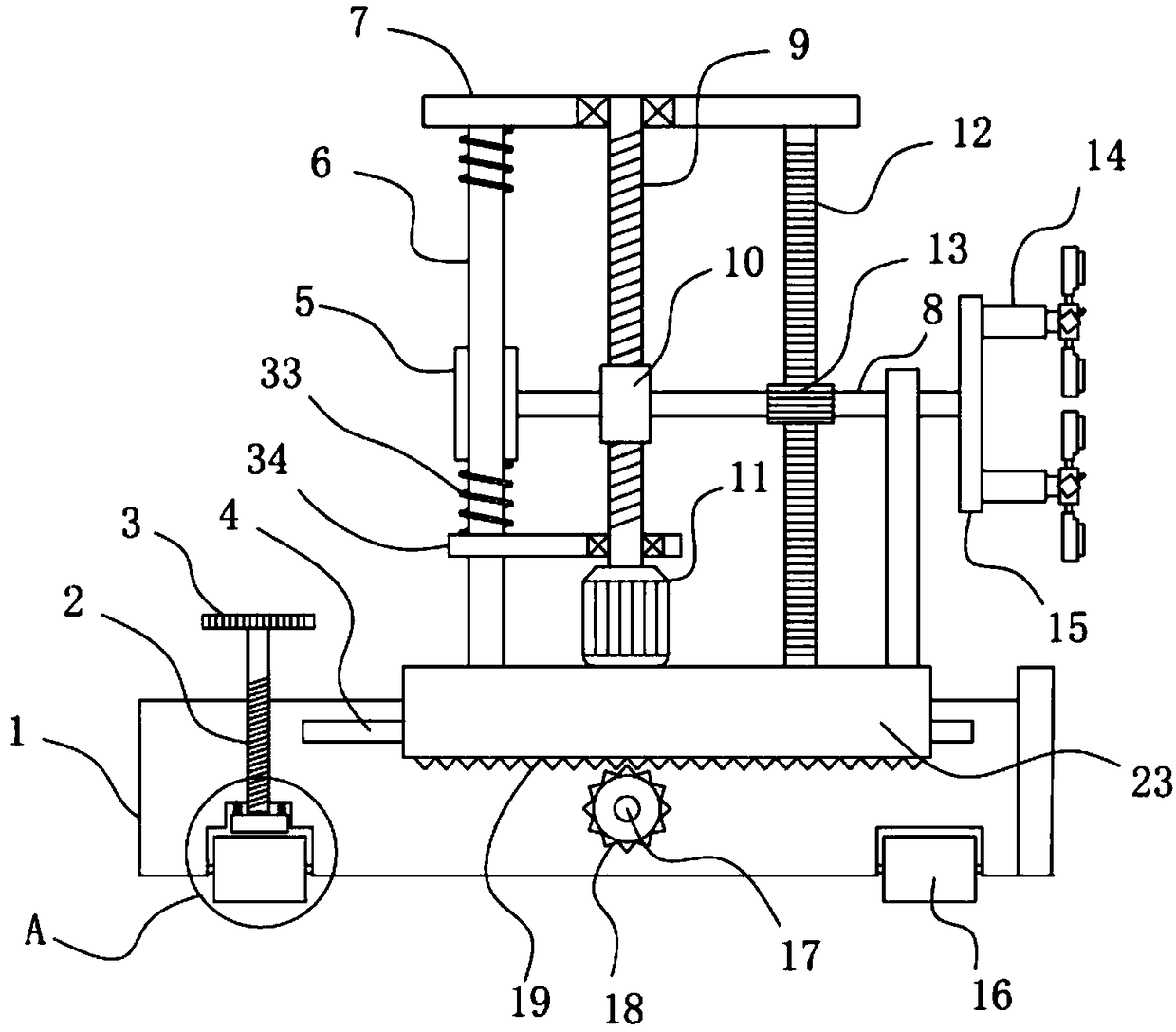
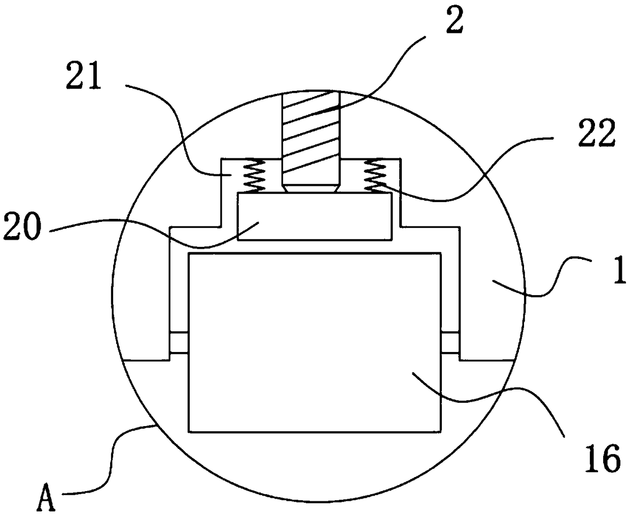
[0027] see figure 1 and Figure 4 As shown, a wall scraping device for building construction includes a car body 1, a sliding support frame 23 is slidably installed on the car body 1, a column 6 is vertically and fixedly installed on the sliding support frame 23, and the top of the column 6 is fixed and installed horizontally There is a top plate 7, and the forward and reverse motor I11 is fixedly installed on the sliding support frame 23. The side wall of the car body 1 is provided with a guide groove 4 in the transverse direction, and the inner side wall of the sliding support frame 23 is fixedly installed with a slide embedded in the guide groove 4. The slider 27, the slider 27 can move left and right along the car body 1 along with the sliding supporting frame 23, and the sliding block 27 is slidably matched with the guide groove 4 to play a guiding role to the sliding supporting frame 23, improving the stability of its sliding .
[0028] The car body 1 is provided with ...
Embodiment 2
[0032] On the basis of Example 1, such as figure 1 , Figure 5 , Figure 7 and Figure 8 As shown, in addition, the skin scraping mechanism includes a rotating disk 15 fixed coaxially with the right end of the rotating shaft 8, and several rotating seats 14 are horizontally fixed on the right side wall of the rotating disk 15, and a sliding column 29 is connected to the rotating seat 14 in transmission, and the sliding column 29 is fixed with a connection seat 30, and the edge of the connection seat 30 is circumferentially fixedly equipped with several knife holders 31. On the knife holder 31, a blade 32 is fixedly installed on the side away from the sliding column 29. The angle between the knife holder 31 and the vertical plane is 15-30 degrees; the rotating shaft 8 drives the rotating disk 15 to rotate, and the rotating disk 15 drives the rotating seat 14 together with the sliding column 29 to realize the rotation of the connecting seat 30, and the connecting seat 30 drive...
Embodiment 3
[0034] On the basis of Example 2, such as figure 1 , Figure 5 and Figure 6 As shown, in addition, the rotating seat 14 is a hollow structure, and the sliding post 29 is slidably installed in the rotating seat 14. The inner side wall of the rotating seat 14 is provided with a chute 28 along the length direction of the rotating seat 14, and the side wall of the sliding post 29 is fixedly installed with a sliding The sliding block 27 embedded in the chute 28 is provided with a limiting spring 26 in the rotating seat 14, and the two ends of the limiting spring 26 are respectively fixed on the rotating seat 14 and the sliding column 29. When the blade 32 is scraping the skin, due to the unevenness of the wall surface, when encountering a larger protrusion on the wall surface, the sliding column 29 will generate a small amplitude in the rotating seat 14 under the elastic force of the limit spring 26. The movement acts as an elastic buffer for the blade 32 to ensure the smoothnes...
PUM
 Abstract
Description
Claims
Application Information
 - R&D
- Intellectual Property
- Life Sciences
- Materials
- Tech Scout
- Unparalleled Data Quality
- Higher Quality Content
- 60% Fewer Hallucinations
Browse by: Latest US Patents, China's latest patents, Technical Efficacy Thesaurus, Application Domain, Technology Topic, Popular Technical Reports.
© 2025 PatSnap. All rights reserved.Legal|Privacy policy|Modern Slavery Act Transparency Statement|Sitemap|About US| Contact US: help@patsnap.com


