A push-and-shake combined wave generator
What is Al technical title?
Al technical title is built by PatSnap Al team. It summarizes the technical point description of the patent document.
A wave-making machine and combined technology, which is applied in the testing of machines/structural components, instruments, measuring devices, etc., can solve the problems of reducing experiment efficiency and increasing experiment cost
Active Publication Date: 2019-11-22
YANSHAN UNIV
View PDF10 Cites 0 Cited by
Summary
Abstract
Description
Claims
Application Information
AI Technical Summary
This helps you quickly interpret patents by identifying the three key elements:
Problems solved by technology
Method used
Benefits of technology
Problems solved by technology
Due to the different wave-making principles, the push plate type and the rocking plate wave machine have their own characteristics. They are used in different experimental environments. The push plate wave machine is suitable for shallow waters, and the rocking plate wave machine is suitable for deep waters. , due to the complexity and diversity of the experimental requirements, when different waves are required in the experiment, the wave maker with a single motion form can no longer meet the requirements, and the method of replacing the wave maker can only be adopted, which increases the cost of the experiment
However, the existing push-swing combined wave generators at this stage require manual switching during the switching process of horizontal push and swing working modes, which reduces the experimental efficiency.
Method used
Image
Click on the blue label to locate the original text in one second.
Reading with bidirectional positioning of images and text.
Examples
Embodiment Construction
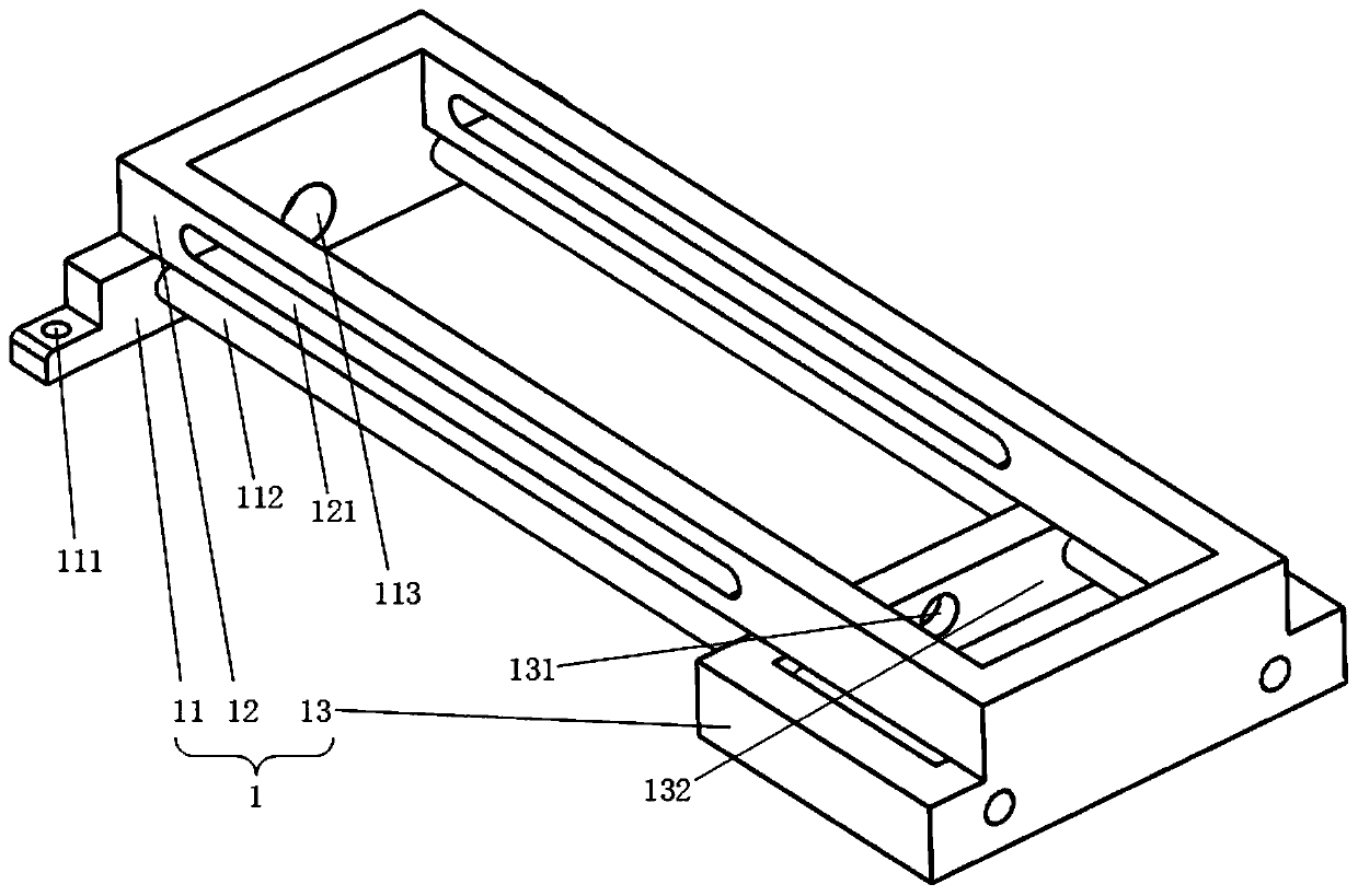
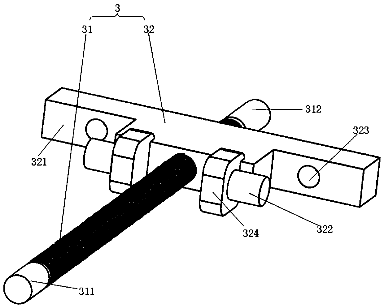
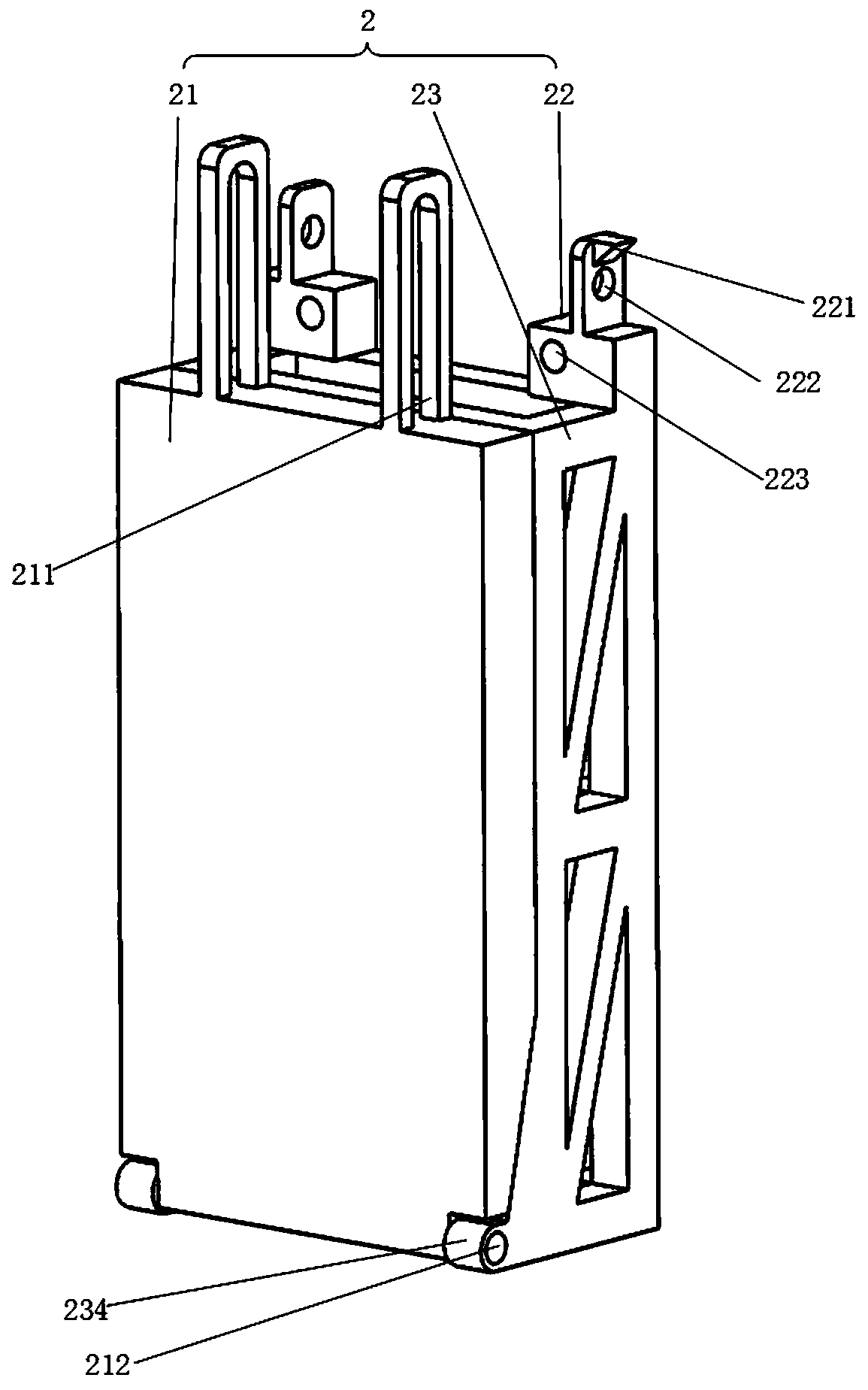
[0026] exist Figure 1 to Figure 10 In the schematic diagram of the present invention, the back seat is a square frame, the back seat is provided with a front end face 52 of the back seat, and a crossbeam 51 is provided in the middle of the top of the back seat. One end of the guide rail support frame of the guide rail support is fixed on the top of the rear seat 5. A second lead screw hole 131 and two groups of guide rail holes are opened on the guide rail support frame, and the positions of the second lead screw holes correspond to the positions of the first lead screw holes. A first lead screw hole 113 and two guide rail holes are opened on the guide rail support boss 11 . The first servo motor 9 is fixed on the rear seat beam, the output end of the first servo motor is connected to the rear end 312 of the lead screw through a coupling, and the lead screw extends to the guide rail support frame through the corresponding second lead screw hole of the guide rail support fram...
PUM
Abstract
The invention discloses a pushing and flapping combined type wave generator mainly comprising components such as a guide rail support, a wave generation plate mechanism, a lead screw and nut mechanism, a switching snap joint, a rear seat, a second servo motor, a driving wheel, a driven wheel, a coupler, a first servo motor, a bearing, a guide rail support boss, a guide rail support main body, a guide rail support frame, a bolt hole, a guide rail, a first guiding groove, a first lead screw hole, a second lead screw hole, a guide rail support frame inner end face, a wave generation plate, a support seat, a wave generation frame and a rotation shaft. According to the pushing and flapping combined type wave generator provided by the invention, pushing and flapping movements of the wave generation plate can be achieved via a set of lead screw and nut transmission mechanism; the switching between two movement modes of pushing and flapping can be automatically, quickly and accurately completed via the switching snap joint; waveform features of waves generated by pushing and flapping are different, so that the waveforms more accordant with experiment requirements can be generated via a pushing-flapping-pushing combined wave generation mode, a flapping-pushing-flapping combined wave generation mode, a pushing-flapping-flapping combined wave generation mode or a flapping-pushing-pushingcombined wave generation mode.
Description
technical field [0001] The invention relates to the field of ocean engineering and experimental research of ports and offshore engineering, in particular to a push-rock combined wave maker. Background technique [0002] In the field of marine engineering and port and offshore engineering experimental research, due to geographical factors and the complexity and uncertainty of the marine environment, outdoor field experiments often have certain risks. Researchers usually use laboratory flume wave-making technology to simulate ocean waves. Wave simulation is an important experimental method, and wave-making machines are necessary experimental devices for flume experiments. According to the different motion forms of the wave-making plate, it can be divided into push plate type and rocking plate type wave maker. The push-plate wave maker realizes the simulation of waves by pushing the wave-making plate along the horizontal direction; the rocking-plate wave maker realizes the wav...
Claims
Application Information
Patent Timeline
Application Date:The date an application was filed.
Publication Date:The date a patent or application was officially published.
First Publication Date:The earliest publication date of a patent with the same application number.
Issue Date:Publication date of the patent grant document.
PCT Entry Date:The Entry date of PCT National Phase.
Estimated Expiry Date:The statutory expiry date of a patent right according to the Patent Law, and it is the longest term of protection that the patent right can achieve without the termination of the patent right due to other reasons(Term extension factor has been taken into account ).
Invalid Date:Actual expiry date is based on effective date or publication date of legal transaction data of invalid patent.