
Electrical automatic regulating transformer

Inactive Publication Date: 2018-11-30
BAOJI UNIV OF ARTS & SCI
View PDF13 Cites 1 Cited by
  • Summary
  • Abstract
  • Description
  • Claims
  • Application Information

AI Technical Summary

Problems solved by technology

[0002] The regulated switching power supply is composed of a full-wave rectifier, a switching tube, an excitation signal, a freewheeling diode, an energy storage inductor and a filter capacitor. The disadvantage of the regulated switching power supply is that there is a relatively serious switching interference
In the stabilized switching power supply, the power adjustment switching transistor works in the best state, and the AC voltage and current generated by it will generate spike interference and vibration interference through other components in the circuit. If these interferences are not suppressed, eliminated and Shielding will seriously affect the normal work of the whole machine
In addition, because the stabilized switching power supply oscillator does not have the isolation of the power frequency transformer, these interferences will be connected to the power frequency grid in series, causing serious interference to other nearby electronic instruments, equipment and household appliances.
At present, the isolation cover is mainly used to isolate the electromagnetic field, but the use of the isolation cover may cause electromagnetic leakage and affect heat dissipation
It affects the automatic voltage regulation operation of the transformer, and there is room for improvement

Method used


Image

  • Electrical automatic regulating transformer
  • Electrical automatic regulating transformer

Examples


Embodiment Construction

[0013] The present invention will be further described below in conjunction with accompanying drawing:

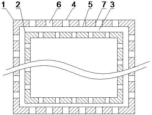
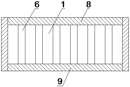
[0014] Such as figure 1 and figure 2 As shown, a voltage-stabilized switching power supply of the present invention includes an outer shell 1, an inner shell 2, an upper side plate 8 and a lower side plate 9, the inner shell 2 is arranged inside the outer shell 1, and the inner surface of the outer shell 1 and the inner shell 2 A gap 3 is provided between the inner sides of the outer shell 1 and the inner shell 2. The upper end faces of the outer shell 1 and the inner shell 2 are connected with the lower side of the upper side plate 8, and the lower end faces of the outer shell 1 and the inner shell 2 are connected with the upper side of the lower side plate 9. The outer shell 1 and the inner shell 2 are provided with a plurality of strip-shaped holes 6, the strip-shaped holes 6 on the outer shell 1 and the strip-shaped holes 6 on the inner shell 2 are misplaced, and the ...


PUM


Abstract

The invention discloses an electrical automatic regulating transformer. The electric automatic regulating transformer. The electric automatic regulating transformer comprises an outer shell, an innershell, an upper side plate and a lower side plate, the inner shell is arranged in the outer shell, a gap is formed between the inner side face of the outer shell and the inner side face of the inner shell, the upper end faces of the outer shell and the inner shell are connected with the lower side face of the upper side plate, the lower end faces of the outer shell and the inner shell are connected with the upper side face of the lower side plate, the outer shell and the inner shell are provided with a plurality of strip-shaped holes, and the strip-shaped holes in the outer shell and the innershell are formed in a misplaced mode. The voltage stable type switch power source achieves effective electromagnetic separation under the situation that heat dissipation is not affected by arrangingthe shells on the two sides, and forming the strip-shaped holes in the shells in a misplaced mode, meanwhile, the shells are filled with electric conductive liquid, and electromagnetic leakage can beeffectively avoided.

Description

technical field [0001] The invention relates to a power supply, in particular to an electric automatic voltage regulating transformer. Background technique [0002] The regulated switching power supply is composed of a full-wave rectifier, a switching tube, an excitation signal, a freewheeling diode, an energy storage inductor and a filter capacitor. The disadvantage of the regulated switching power supply is that there is a relatively serious switching interference. In the stabilized switching power supply, the power adjustment switching transistor works in the best state, and the AC voltage and current generated by it will generate spike interference and vibration interference through other components in the circuit. If these interferences are not suppressed, eliminated and Shielding will seriously affect the normal work of the whole machine. In addition, because the stabilized switching power supply oscillator does not have the isolation of the power frequency transforme...

Claims


Application Information

Patent Timeline
IPC IPC(8): H01F27/02H01F27/08H01F27/34H01F27/36H01F29/00
CPCH01F27/02H01F27/025H01F27/08H01F27/34H01F27/346H01F27/36H01F29/00
Inventor 欧卫斌
Owner BAOJI UNIV OF ARTS & SCI
Learn More