Isolation switch and electric pole assembly

A technology of isolating switches and electric poles, which is applied in the field of power system application equipment, can solve the problems of long time-consuming to connect the ground wire and reduce maintenance efficiency, and achieve the effects of saving maintenance time, improving maintenance efficiency, and shortening time-consuming

Inactive Publication Date: 2018-11-30
GUANGDONG POWER GRID CO LTD +1
View PDF5 Cites 6 Cited by
  • Summary
  • Abstract
  • Description
  • Claims
  • Application Information

AI Technical Summary

Problems solved by technology

[0005] The purpose of the present invention is to provide an isolating switch to solve the technical problems in the prior...

Method used


Image

  • Isolation switch and electric pole assembly
  • Isolation switch and electric pole assembly
  • Isolation switch and electric pole assembly

Examples


Embodiment 1

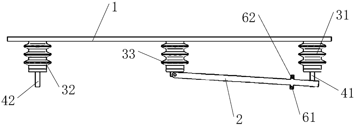
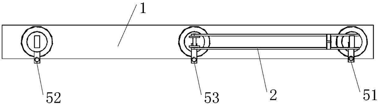
[0044] see Figure 1-Figure 3 As shown, this embodiment provides an isolating switch, including a base 1 and a knife switch 2;

[0045] The base 1 is connected to the first moving contact 41 through the first insulator 31 , the second moving contact 42 is connected through the second insulator 32 , and the static contact is connected through the third insulator 33 ;

[0046] The first connecting terminal 51 is connected to the first moving contact 41, the second connecting terminal 52 is connected to the second moving contact 42, the third connecting terminal 53 is connected to the static contact, and the The first connecting terminal 51 is used for connecting to a power supply, the second connecting terminal 52 is used for grounding, and the third connecting terminal 53 is used for connecting a load;

[0047] The first end of the knife switch 2 is rotatably connected to the static contact, and when the first end of the knife switch 2 rotates relative to the static contact, t...

Embodiment 2

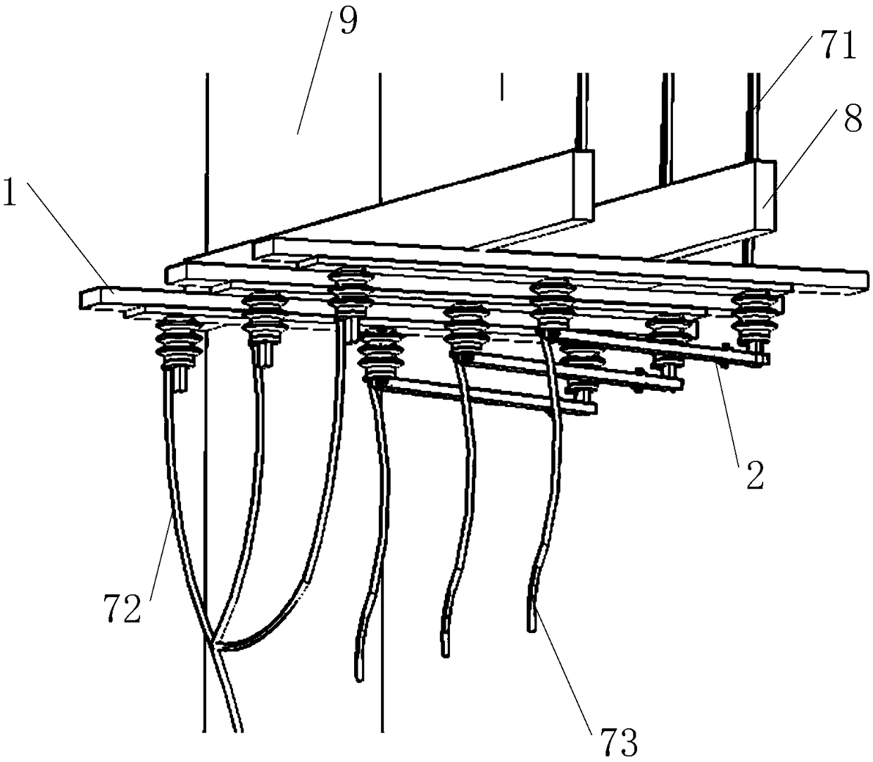
[0088] Embodiment 2 provides a pole assembly, which includes the isolating switch described in Embodiment 1. The technical features of the isolating switch disclosed in Embodiment 1 are also applicable to this embodiment. The disclosed The technical characteristics of the isolating switch will not be described repeatedly. The implementation of the pole assembly will be further described in detail below in conjunction with the accompanying drawings.

[0089] In order to save space, the improved features of this embodiment are also reflected in Figure 1-Figure 3 in, therefore, combined with Figure 1-Figure 3 The configuration of this example will be described.

[0090] see Figure 1-Figure 3 As shown, the pole assembly provided in this embodiment includes the isolating switch and the pole 9;

[0091] The base 1 is detachably connected to the pole 9 .

[0092] It further solves the technical problem in the prior art that it takes a long time to connect the distribution tra...


PUM


Abstract

The invention relates to the technical field of electric power system application equipment, in particular to an isolation switch and an electric pole assembly. The isolation switch comprises a base and a knife switch; the base is connected with a first moving contact through a first insulator, connected with a second moving contact through a second insulator, and connected with a static contact through a third insulator; the first moving contact is connected with a first wiring terminal; the second moving contact is connected with a second wiring terminal; the static contact is connected witha third wiring terminal; and the first end of the knife switch is rotationally connected with the static contact, and the second end can be closed with or separated from the first moving contact andthe second moving contact separately. The electric pole assembly comprises the isolation switch. By virtue of the isolation switch and the electric pole assembly provided by the invention, the technical problems that hanging of a grounding wire of a distribution transformer takes relatively long time, and the overhauling efficiency of the distribution transformer is lowered in the prior art are solved.

Description

technical field [0001] The invention relates to the technical field of power system application equipment, in particular to an isolating switch and a pole assembly. Background technique [0002] Distribution transformer, referred to as "distribution transformer", refers to a static electrical device used in power distribution system to transform AC voltage and current according to the law of electromagnetic induction and transmit AC power. China's transformer products can generally be divided into UHV (750KV and above), ultra-high voltage (500KV) transformers, 220-110KV transformers, and 35KV and below transformers according to their voltage levels. Distribution transformers usually refer to power transformers operating in the distribution network with a voltage level of 10-35KV and a capacity of 6300KVA and below to directly supply power to end users. [0003] According to statistics, it takes about 30 minutes to 40 minutes to change the distribution transformer from the o...

Claims


Application Information

Patent Timeline
IPC IPC(8): H01H31/02H01H31/26
CPCH01H31/02H01H31/026H01H31/26
Inventor 葛阳李龙桂宁文保刘国艺成文强罗杨胜
Owner GUANGDONG POWER GRID CO LTD
Why Eureka
Try Eureka