Dual-polarization filter antenna for suppressing high cross-polarization ratio outside the broadband

A dual-polarization and antenna technology, which is applied in the direction of slot antenna, antenna grounding device, antenna grounding switch structure connection, etc., can solve the problems of poor filter antenna high selectivity and low cross-polarization ratio

Active Publication Date: 2020-01-31
HUAWEI TECH CO LTD +1
View PDF7 Cites 0 Cited by
  • Summary
  • Abstract
  • Description
  • Claims
  • Application Information

AI Technical Summary

Problems solved by technology

[0005] The purpose of the present invention is to provide a dual-polarized filter antenna that suppresses high cross-polarization ratios outside the broadband, to solve the problems of poor high selectivity and low cross-polarization ratio in the 0° direction for existing filter antennas, Realize the highly selective filtering function of the antenna and improve the cross-polarization ratio of the antenna in the 0° direction

Method used


Image

  • Dual-polarization filter antenna for suppressing high cross-polarization ratio outside the broadband
  • Dual-polarization filter antenna for suppressing high cross-polarization ratio outside the broadband
  • Dual-polarization filter antenna for suppressing high cross-polarization ratio outside the broadband

Examples


Embodiment 1

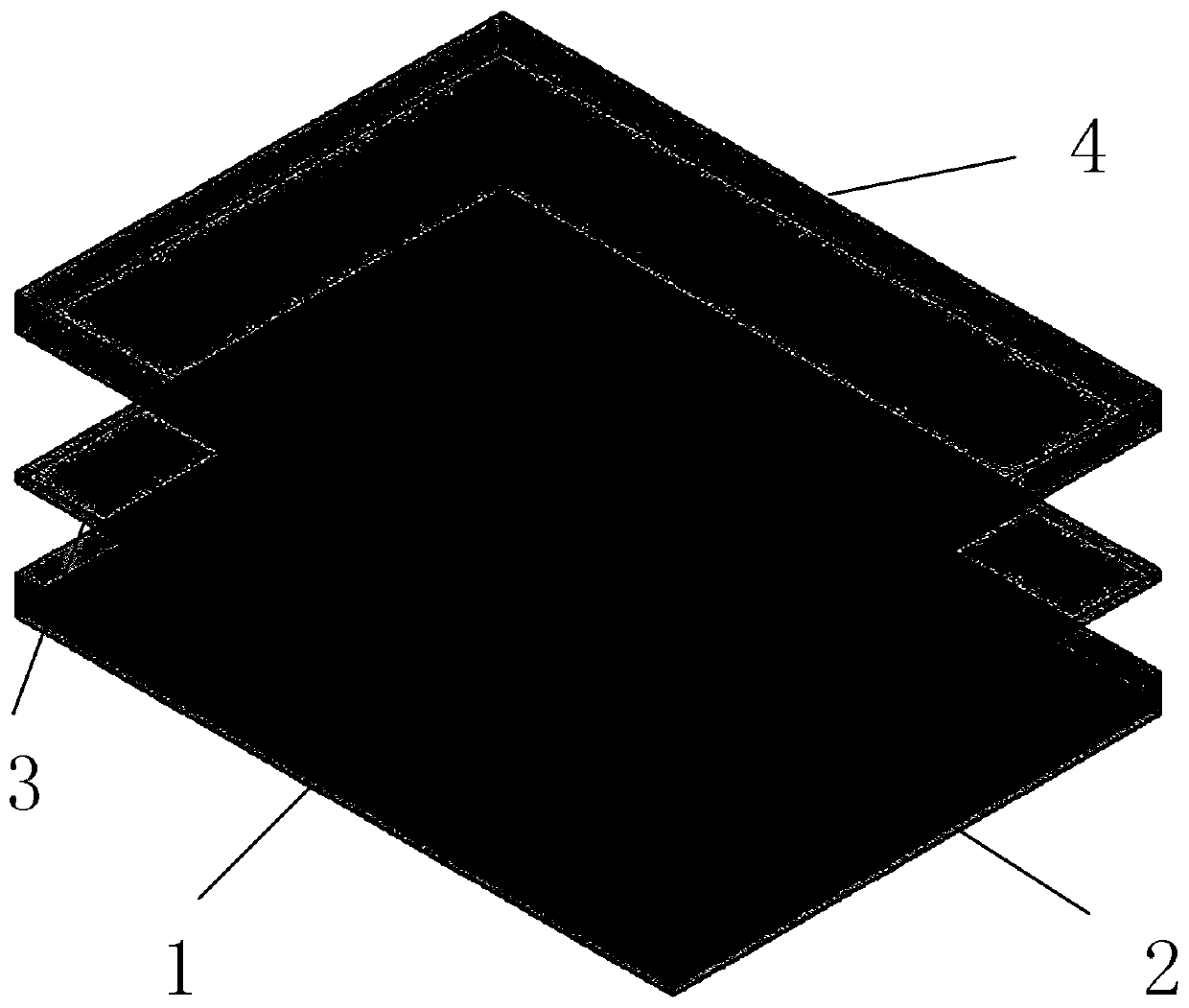
[0022] refer to figure 1 , the highly selective filter antenna of the present invention includes a feed network structure 1, an antenna main structure 2, a coupling radiation structure 3 and a radome 4. The main structure 2 is located directly above and connected to the feeding network structure 1, the coupling radiation structure 3 is located above the main structure 2, and the radome 4 is located above the upper coupling radiation structure 3, forming an upper, middle and lower three-layer structure.

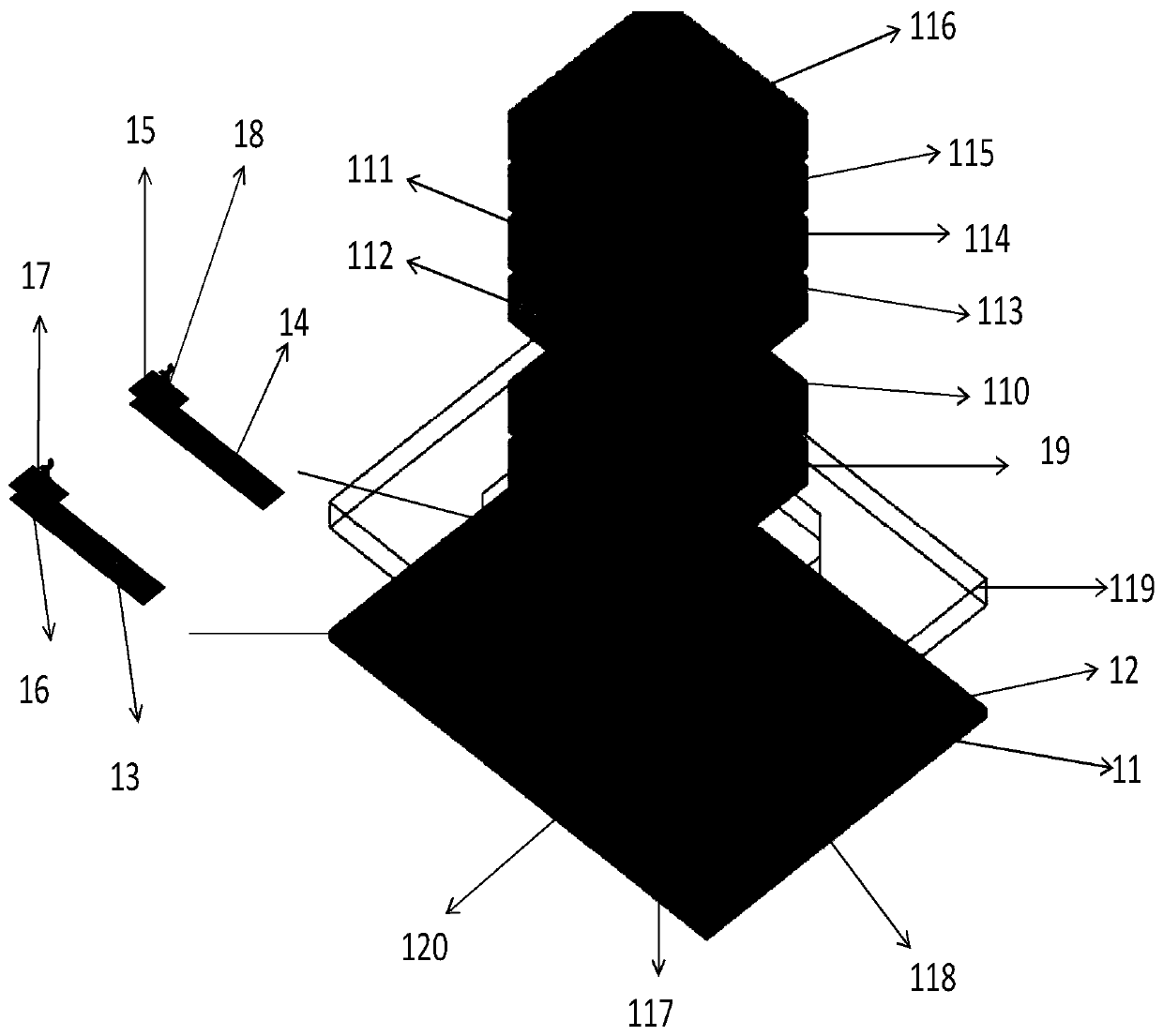
[0023] refer to figure 2, the lower feeder network 1 includes a first lower dielectric plate 11, a first lower metal floor 12, a first microstrip feeder 13, a second microstrip feeder 14, a first balun feeder structure 17, a second Balun feed structure 18, second lower metal floor 19, second lower dielectric plate 110, first power divider 111, second power divider 112, first lower transition layer 113, third lower dielectric plate 114, second Three lower metal floors 115 , ...

Embodiment 2

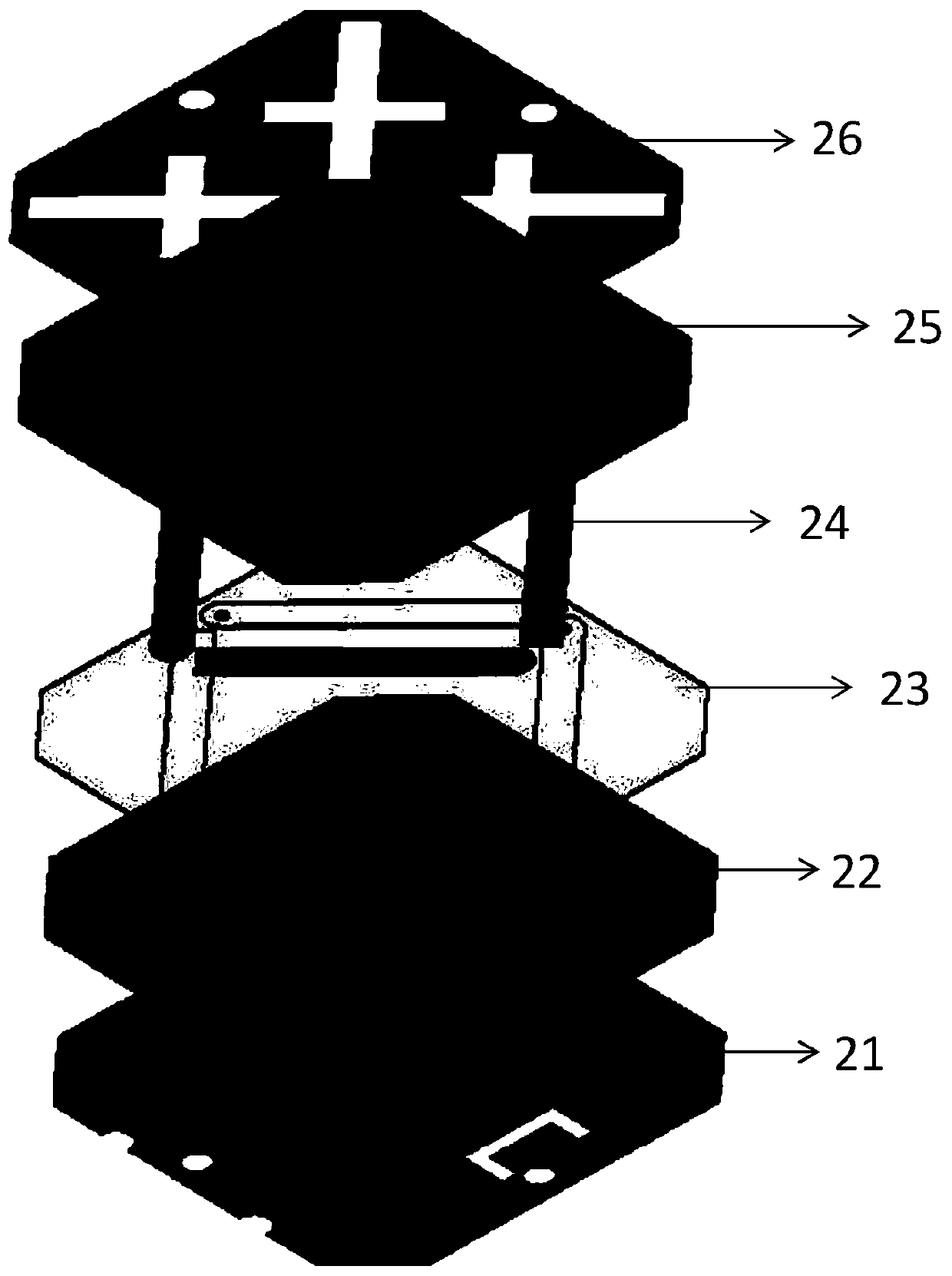
[0036] The overall structure of this example is the same as that of Embodiment 1, except that two L-shaped slits are etched along the center of the antenna on the middle floor 21, and the effect of the L-shaped slits on improving the cross-polarization ratio compared with the C-shaped slits in Embodiment 1 It is more obvious, but the L-shaped gap also has a certain deterioration effect on the isolation between the two ports of the antenna.

[0037] Effect of the present invention can be further illustrated by the following simulation results:

[0038] The length, width and height of the first lower dielectric plate 11 are respectively 43mm, 58mm and 0.762mm, and the dielectric constant is 3.0; the length and width of the first lower metal floor 12 are respectively 43mm and 58mm, and the side length of the square groove is 1.27mm, the length and width of the rectangular slot are 4.6mm and 3mm respectively; the length and width of the first microstrip feeder 13 are 11.135mm and ...


PUM

PropertyMeasurementUnit
thicknessaaaaaaaaaa
thicknessaaaaaaaaaa
thicknessaaaaaaaaaa

Abstract

The invention discloses a high-selectivity and low-profile microstrip dual-polarization filtering antenna and mainly solves the problems of relatively poor high selectivity and relatively low cross polarization ratio in a zero-degree direction of a traditional filtering antenna. The high-selectivity and low-profile microstrip dual-polarization filtering antenna comprises a low-layer feeding network structure (1), an intermediate-layer main body structure (2), an upper-layer coupling radiation structure (3) and an antenna cover (4) from bottom to top, the intermediate-layer main body structure(2) comprises an intermediate-layer floor (21) and a cross coupling slot radiation structure (26), a group of slots are etched in the intermediate-layer floor (21), are same in shape, are centricallysymmetric to an antenna center and are used for achieving high cross polarization ratio of the antenna in an axial direction. The group of cross coupling slots perpendicular to each other are etched on the cross coupling slot radiation structure (26), and four rectangular grooves perpendicular to the cross coupling slots are etched and are used for achieving wideband external inhibition of the antenna. By the high-selectivity and low-profile microstrip dual-polarization filtering antenna, the cross polarization ratio in the zero-degree direction is improved, the filtering effect of the antennais improved, and the high-selectivity and low-profile microstrip dual-polarization filtering antenna can be used for wireless communication.

Description

technical field [0001] The invention belongs to the technical field of wireless communication, and relates to a dual-polarization filter antenna, which can be used in civil wireless communication systems. Background technique [0002] With the continuous development of modern electronic technology and information technology, more and more electronic devices meeting different requirements and various antennas are integrated on a limited platform, which requires fewer devices to Realize more functions. Antennas and filters are the most common and important passive components in wireless communication front-ends, and their performance often directly affects the performance of the entire communication system. At the same time, compared with other components in the front end, the antenna and filter have a larger size. Therefore, the miniaturization of the antenna and filter is the key to the miniaturization of the wireless communication front end. Multiple antennas are densely ...

Claims


Application Information

Patent Timeline
Patent Type & Authority Patents(China)
IPC IPC(8): H01Q1/38H01Q1/48H01Q1/50H01Q13/10
CPCH01Q1/38H01Q1/48H01Q1/50H01Q13/10
Inventor 翟会清王华红魏子淳马少波郑立成周翔宇李佳旭
Owner HUAWEI TECH CO LTD
Why Eureka
Try Eureka