
Dry film pressing equipment for single-sided circuit board, and using steps thereof

A technology of circuit board and dry film pressing, which is applied in the direction of printed circuit, printed circuit manufacturing, electrical components, etc., to achieve the effect of quickly changing the film pressure, good effect and simple structure

Inactive Publication Date: 2018-11-30
BEIHAI HIBOSE TECH CO LTD
View PDF0 Cites 1 Cited by
  • Summary
  • Abstract
  • Description
  • Claims
  • Application Information

AI Technical Summary

Problems solved by technology

[0003] In the existing technology, the single-sided circuit board and the dry film are generally bonded by the upper and lower pressure rollers, but for different PCB boards, the dry film lamination pressure is different, so a quick-change pressure roller has been developed. spacing, so as to achieve rapid change of pressing roller pressure dry film equipment has become an urgent problem to be solved by those skilled in the art

Method used


Image

  • Dry film pressing equipment for single-sided circuit board, and using steps thereof
  • Dry film pressing equipment for single-sided circuit board, and using steps thereof
  • Dry film pressing equipment for single-sided circuit board, and using steps thereof

Examples


Embodiment Construction

[0023] The following will clearly and completely describe the technical solutions in the embodiments of the present invention with reference to the accompanying drawings in the embodiments of the present invention. Obviously, the described embodiments are only some, not all, embodiments of the present invention. Based on the embodiments of the present invention, all other embodiments obtained by persons of ordinary skill in the art without making creative efforts belong to the protection scope of the present invention.

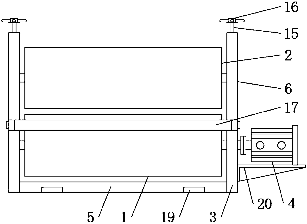
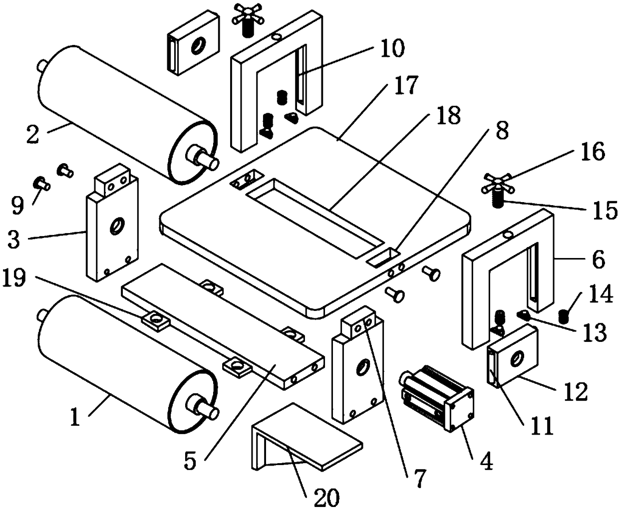
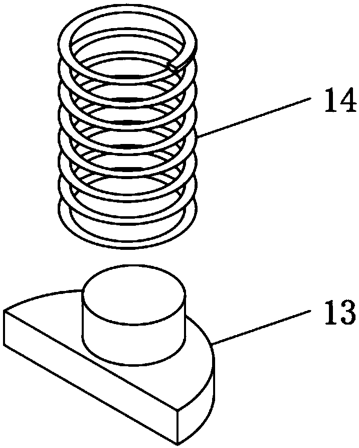
[0024] see Figure 1-3 , the present invention provides a technical solution: a dry film pressing equipment for single-sided circuit boards, including a lower pressing roller 1 and an upper pressing roller 2, the left and right ends of the rotating shaft of the lower pressing roller 1 are bearings connected to the support plate 3, and the rotating shaft runs through After the support plate 3 is coaxially connected to the output shaft of the stepper motor 4 thr...


PUM


Abstract

The invention discloses dry film pressing equipment for a single-sided circuit board. The dry film pressing equipment comprises a lower pressing roller and an upper pressing roller; supporting framesare arranged on the two sides of the upper pressing roller, sliding grooves are formed in the supporting frames, sliding blocks are embedded into the sliding grooves, the sliding blocks are fixedly connected with moving bearing seats, and the moving bearing seats are on bearing connection with the upper pressing roller; and the tops of the supporting frames are in threaded connection with bolt columns, and the bolt columns are connected with the tops of the moving bearing seats in an abutted mode. The invention further discloses using steps of the dry film pressing equipment for the single-sided circuit board. The using steps adopt the following steps that S1, a rotating piece is screwed; S2, an electric heating wire inside the upper pressing roller is started; S3, two raw materials are introduced between the lower pressing roller and the upper pressing roller; and S4, a stepping motor is started. According to the dry film pressing equipment for the single-sided circuit board and the using steps thereof, the structure is concise, scientific and reasonable, the spacing between the lower pressing roller and the upper pressing roller can be quickly changed through the extrusion effectof the bolt columns on the moving bearing seats, thus the film pasting pressure is quickly changed, the film pasting speed is precisely controlled through the stepping motor, and the steps of dry film pressing operation are easy and convenient.

Description

technical field [0001] The invention relates to a dry film pressing device for a single-sided circuit board, in particular to a dry film pressing device for a single-sided circuit board and its use steps. Background technique [0002] On the most basic PCB, parts are concentrated on one side, and wires are concentrated on the other side. Since the wires only appear on one side, this PCB is called a single-sided circuit board. The dry film is a polymer compound, which can produce a polymerization reaction after being irradiated by ultraviolet rays to form a stable substance attached to the board surface, so as to achieve the function of blocking electroplating and etching. [0003] In the existing technology, the single-sided circuit board and the dry film are generally bonded by the upper and lower pressure rollers, but for different PCB boards, the dry film lamination pressure is different, so a quick-change pressure roller has been developed. The dry film pressing equipm...

Claims


Application Information

Patent Timeline
IPC IPC(8): H05K3/00
CPCH05K3/00
Inventor 吴楚鸿李纬陈巧银黄泽杭罗桂容徐乐山
Owner BEIHAI HIBOSE TECH CO LTD
Learn More