Injection mould lifting device

A technology for lifting equipment and injection molds, which is applied in the directions of cranes, load hanging components, transportation and packaging, etc. It can solve the problems that the mold needs to be moved, the mold is heavy, and it is difficult to move manually, so as to reduce the pulling force and facilitate the movement.

Inactive Publication Date: 2018-12-04
无锡有孚精工科技有限公司
View PDF6 Cites 2 Cited by
  • Summary
  • Abstract
  • Description
  • Claims
  • Application Information

AI Technical Summary

Problems solved by technology

[0003] The technical problem to be solved by the present invention is that the mold needs to be moved before and after installation, and the mold is heavy and difficult to move manually. A lifting device for injection molds is provided to solve the above problems

Method used


Image

  • Injection mould lifting device
  • Injection mould lifting device
  • Injection mould lifting device

Examples


Embodiment

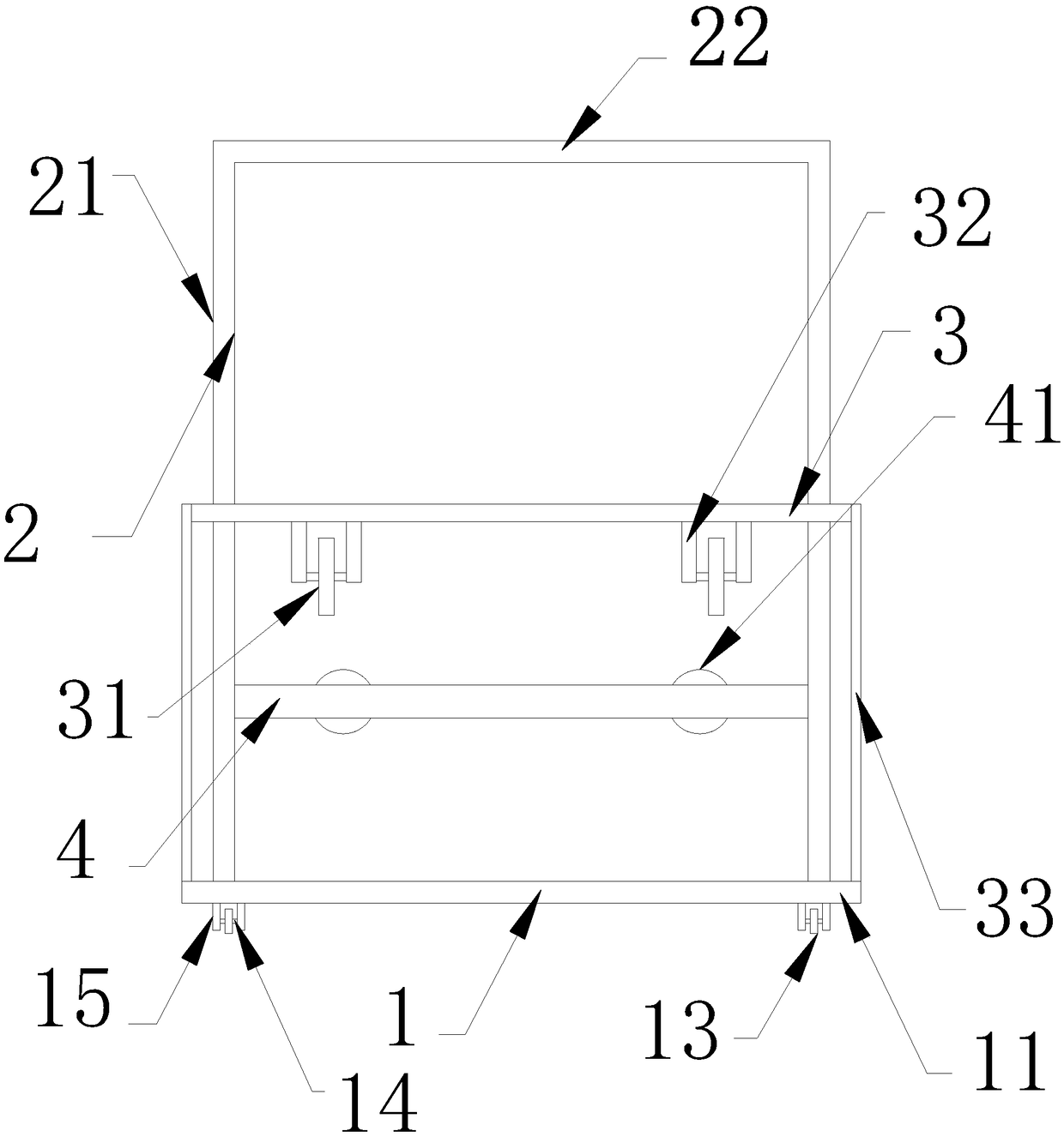
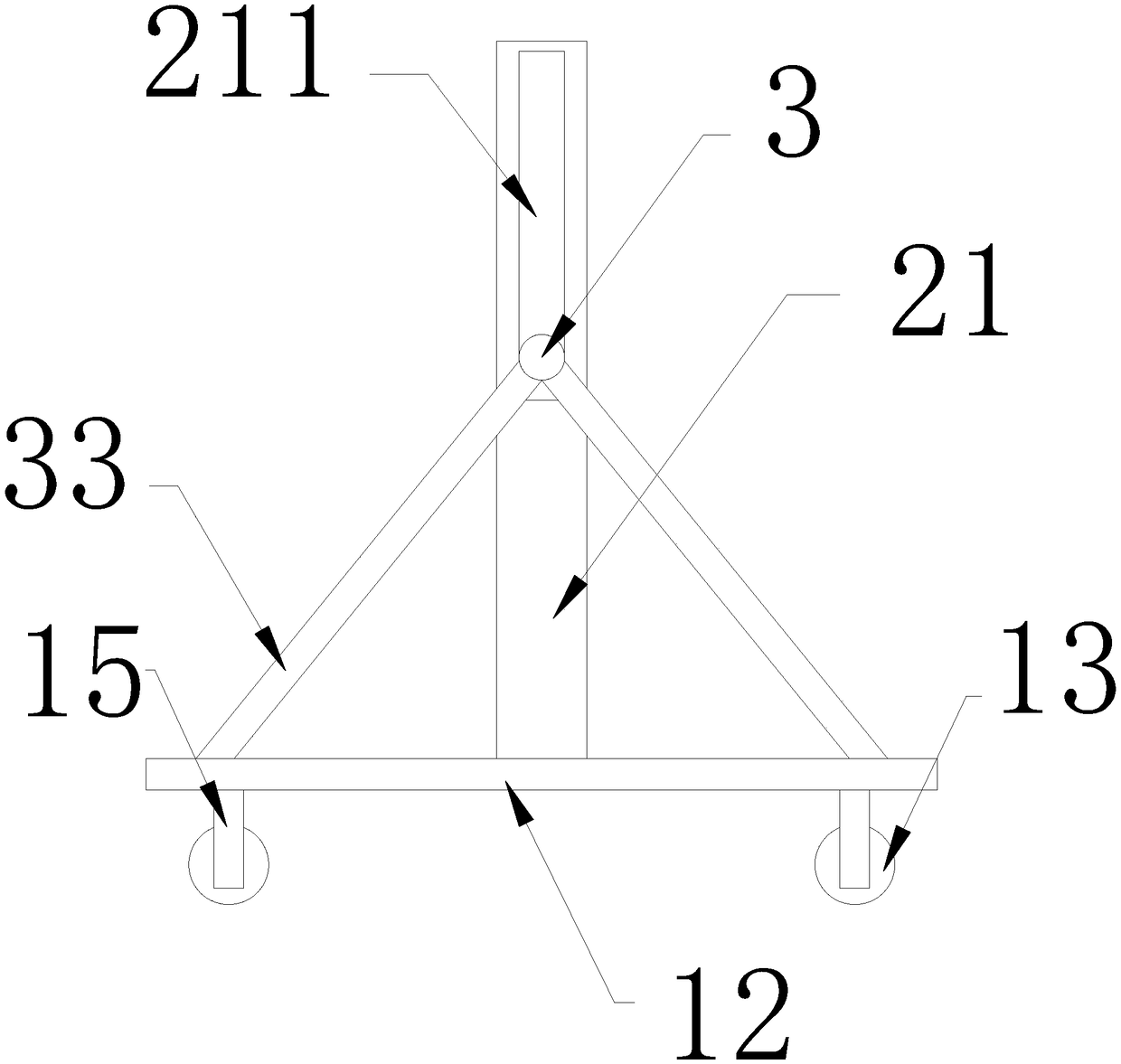
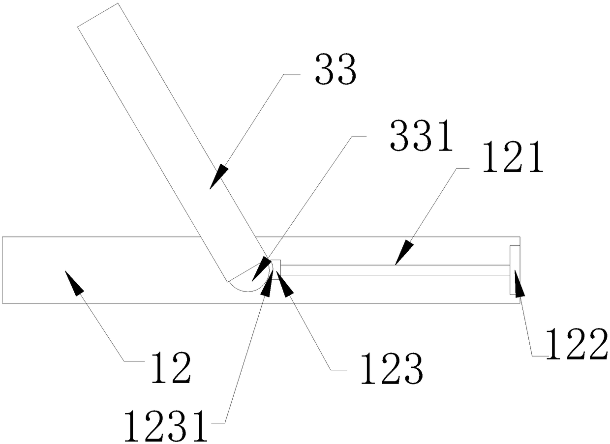
[0022] Example: such as Figure 1-5 As shown, the present invention provides a lifting device for an injection mold, comprising a horizontal frame 1, a vertical frame 2, a lifting rod 3, a steering rod 4 and a controller, and the horizontal frame 1 includes a first frame rod 11, a second Two frame bars 12, the first frame bar 11, the second frame bar 12 are all provided with two, the first frame bar 11, the second frame bar 12 are mutually connected into a rectangular frame; the vertical frame 2 includes a third There are two frame rods 21, a fourth frame rod 22, and two third frame rods 21. One end of the third frame rod 21 is fixedly arranged in the middle of the second frame rod 12, and the other end is connected to the fourth frame rod 22; Said lifting rod 3 passes through the third frame rod 21, and two ends are provided with movable struts 33; said movable struts 33 are provided with four, and one end of the movable struts 33 is fixed with the third frame rod 21 by a rot...


PUM


Abstract

The invention discloses an injection mould lifting device comprising a horizontal frame, a vertical frame, a lifting rod, a direction adjusting rod and a controller. The horizontal frame comprises twofirst frame rods and two second frame rods; the first frame rods and the second frame rods are connected with each other to form a rectangular frame. The vertical frame comprises two third frame rodsand a fourth frame rod, one end of each third frame rod is fixed in the middle part of the corresponding second frame rod, and the other end of each third frame rod is connected with the fourth framerod. The lifting rod passes through the third frame rods, two ends of the lifting rod are connected with four movable support rods, each end of the lifting rod is provided with two movable support rods, the movable support rods are fixed by rotating shafts, and the tail ends of the movable support rods are arranged on the second frame rods; the lifting rod is provided with lifting wheels; the direction adjusting rod is fixed on the third frame rods and is provided with direction adjusting wheels.

Description

technical field [0001] The invention relates to the technical field of mechanical mold accessories, in particular to an injection mold lifting device. Background technique [0002] The weight of the mold is mostly made of metal, which has a certain weight. In the process of manufacturing, it is inevitable to carry the mold; at the same time, the shape and size of the mold are different, and the height of the installation of the different shapes of the mold is also different. This work is done manually, and it is troublesome to control the lifting of the mold by a forklift or a crane. Contents of the invention [0003] The technical problem to be solved by the present invention is that the mold needs to be moved before and after installation, and the mold is heavy and difficult to move manually. A lifting device for injection mold is provided to solve the above problems. [0004] In order to solve the problems of the technologies described above, the present invention prov...

Claims


Application Information

Patent Timeline
Patent Type & Authority Applications(China)
IPC IPC(8): B66C25/00B66C13/00
CPCB66C25/00B66C13/00
Inventor 黄华才
Owner 无锡有孚精工科技有限公司
Why Eureka
Try Eureka