
Campus plant landscape cultivation device

A cultivation device and plant technology, applied in the field of campus plant landscape cultivation devices, can solve the problems of wasting manpower, increasing labor load, and low efficiency, and achieve the effects of reducing labor costs, improving work efficiency, and flexible and convenient operation

Inactive Publication Date: 2018-12-07
卞浩宇
View PDF4 Cites 7 Cited by
  • Summary
  • Abstract
  • Description
  • Claims
  • Application Information

AI Technical Summary

Problems solved by technology

In order to make the greening of the city or park beautiful, in the greening process, it is necessary to trim and beautify the tall plants, which often make various shapes for the greening plants, such as trimming the irregular plant crowns into a circle or For other shapes, the current trimming and shaping machinery for greening mainly relies on manual operation: manual use of electric scissors and lawn trimming vehicles to complete the trimming, electric scissors require workers to carry the work, which is labor-intensive and low in efficiency; lawn trimmers need to be pushed by workers, It also has a certain labor intensity, and can only cut the fur and grass, and cannot trim seedlings
[0003] In the prior art, there are some devices that can shape the plant landscape with a rectangular shape or a smooth surface, but these devices cannot realize the pruning and modeling of the spherical landscape.
[0004] At the same time, the greening plants also need regular watering and spraying to remove insects and other work. At present, most of these tasks are done manually, which greatly wastes manpower and increases the amount of labor.

Method used


Image

  • Campus plant landscape cultivation device
  • Campus plant landscape cultivation device
  • Campus plant landscape cultivation device

Examples


Embodiment Construction

[0023] In order to better understand the present invention, the implementation manner of the present invention will be explained in detail below in conjunction with the accompanying drawings.

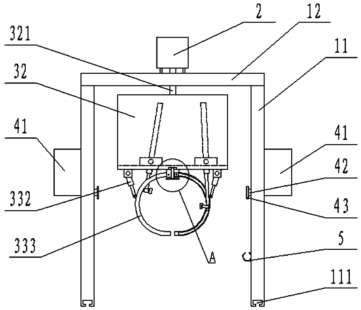
[0024] as attached figure 1 To attach Figure 5 As shown, it includes a mobile frame, a motor 2, a pruning device and a controller. The mobile frame includes four vertically arranged pillars 11 and a horizontally arranged top plate 12. The height of the pillar 11 is greater than the maximum height of the plant landscape, ensuring that the The pruning device can work normally, and the upper end of the pillar 11 is fixed with the top plate 12 by welding. In order to facilitate the movement of the entire cultivation device, slide rails are preset on both sides of the plant landscape, and a slide groove 111 corresponding to the slide rails is opened at the lower end of each pillar 11 .

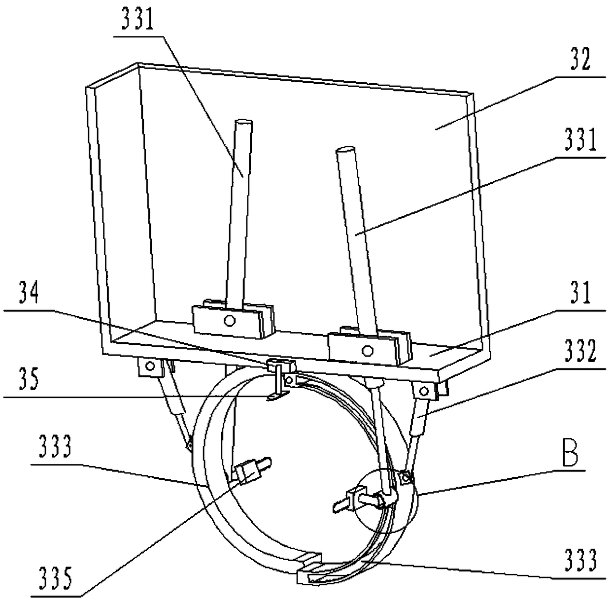
[0025] Trimming device comprises base plate 31, casing 32 and pruning mechanism, casing 32 lower ends ...


PUM


Abstract

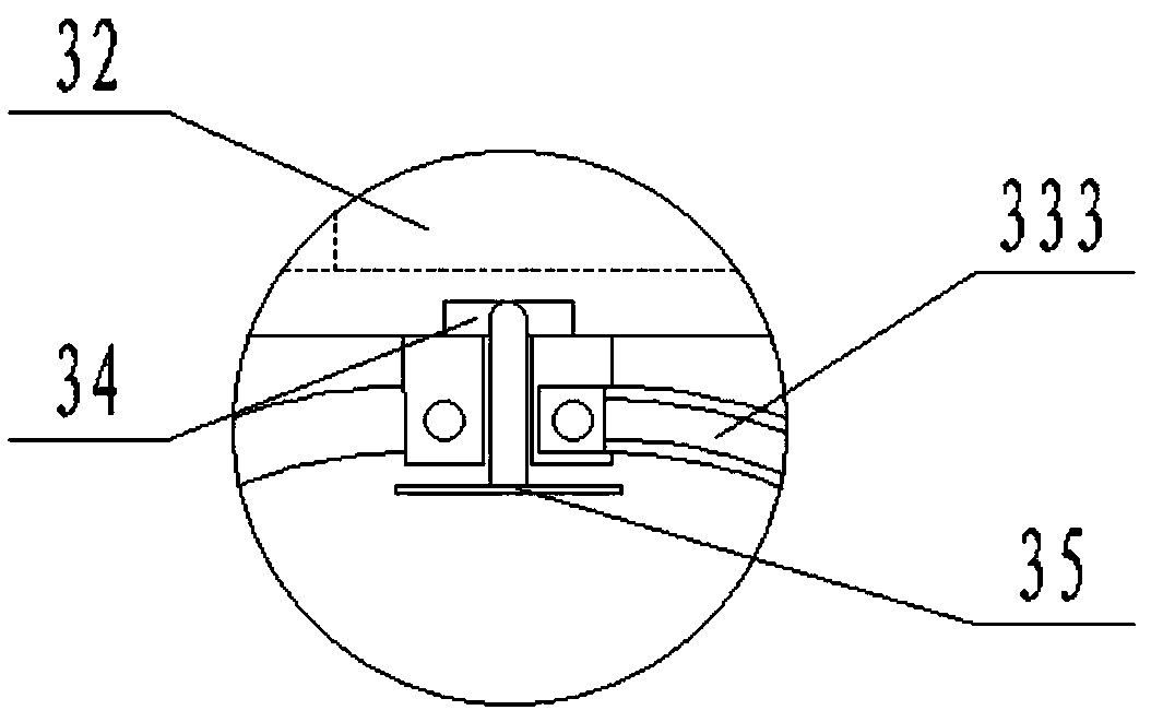
The invention discloses a campus plant landscape cultivation device. The device comprises a moving frame, a motor, a trimming device and a controller, wherein a through hole is arranged at a middle position of the upper end surface of a top plate, and a bearing is arranged in the through hole; a motor is fixed on the top plate; the trimming device comprises a bottom plate, a casing and two sets oftrimming mechanisms, the lower end of the casing is welded to the bottom plate, a rotating shaft is arranged at a middle position of the upper end of the casing, and the rotating shaft is connected to the output end of the motor correspondingly; and each set of the trimming mechanism comprises a first hydraulic cylinder, a second hydraulic cylinder, a curved track groove, a slider and a small electric saw, one end of each curved track groove is hinged to the bottom plate, the sliders and the track grooves are matched, the small electric saws are connected to the sliders through L-shaped rods,the first hydraulic cylinders are hinged to the bottom plate, and the telescopic parts of the first hydraulic cylinders are correspondingly connected with the L-shaped rods, and the second hydrauliccylinders are also hinged to the bottom plate, and the telescopic parts of the second hydraulic cylinders are hinged to the outer sides of the track grooves.

Description

technical field [0001] The invention relates to the technical field of pruning equipment for greening, in particular to a campus plant landscape cultivation device. Background technique [0002] With the development of society and the improvement of living standards, people's requirements for the environment are getting higher and higher. Now most of the streets, roadsides, and vacant areas in most cities and towns are planted with green seedlings, ground grass and other plants to improve air quality and environmental protection. beautify environment. In order to make the greening of the city or park beautiful, in the greening process, it is necessary to trim and beautify the tall plants, which often make various shapes for the greening plants, such as trimming the irregular plant crowns into a circle or For other shapes, the current trimming and shaping machinery for greening mainly relies on manual operation: manual use of electric scissors and lawn trimming vehicles to c...

Claims


Application Information

Patent Timeline
Patent Type & Authority Applications(China)
IPC IPC(8): A01G3/08A01G25/09A01M7/00A01D43/14A01D34/63
CPCA01D34/63A01D43/14A01G3/088A01G25/09A01M7/0042
Inventor 卞浩宇
Owner 卞浩宇
Learn More