Seasoning bottle capable of controlling dosage

A condiment bottle and pouring technology, which is applied in the field of kitchen accessories, can solve the problems of low reliability, large dosage, and high limitations of use, and achieve the effect of improving reliability and reducing limitations of use

Inactive Publication Date: 2018-12-07
鲍若妍
View PDF4 Cites 1 Cited by
  • Summary
  • Abstract
  • Description
  • Claims
  • Application Information

AI Technical Summary

Problems solved by technology

[0002] As we all know, the seasoning bottle is a kind of auxiliary device used for holding kitchen seasonings, so that it is easier to take and use during cooking, and it has been widely used in the field of kitchen supplies; The bottle includes a cup body and a cup cover. The inside of the cup body is provided with a placement cavity, and the top of the cup body is provided with a pick-and-place opening, which communicates with the inside of the placement cavity. The Tongka slot buckle is installed on the upper part of the outer wall of the cup body, and the top inner wall cover of the cup cover is installed on the pick-and-place opening; when the existing seasoning bottle is used, the seasoning is first placed in the placement cavity in advance, and it is directly taken out when in use. And open the cup cover and pour it to the desired seasoning position; in the use of existing seasoning bottles, it is found that due to the large opening of the pick-and-place mouth, direct dumping leads to a large amount of seasoning poured out, and the amount of seasoning poured out cannot be controlled. As a result, its use reliability is low; and it cannot conduct internal observations, and cannot know the types and dosages of internal seasonings in a timely manner, resulting in high limitations in its use;

Method used


Image

  • Seasoning bottle capable of controlling dosage
  • Seasoning bottle capable of controlling dosage
  • Seasoning bottle capable of controlling dosage

Examples


Embodiment Construction

[0016] The specific implementation manners of the present invention will be further described in detail below in conjunction with the accompanying drawings and embodiments. The following examples are used to illustrate the present invention, but are not intended to limit the scope of the present invention.

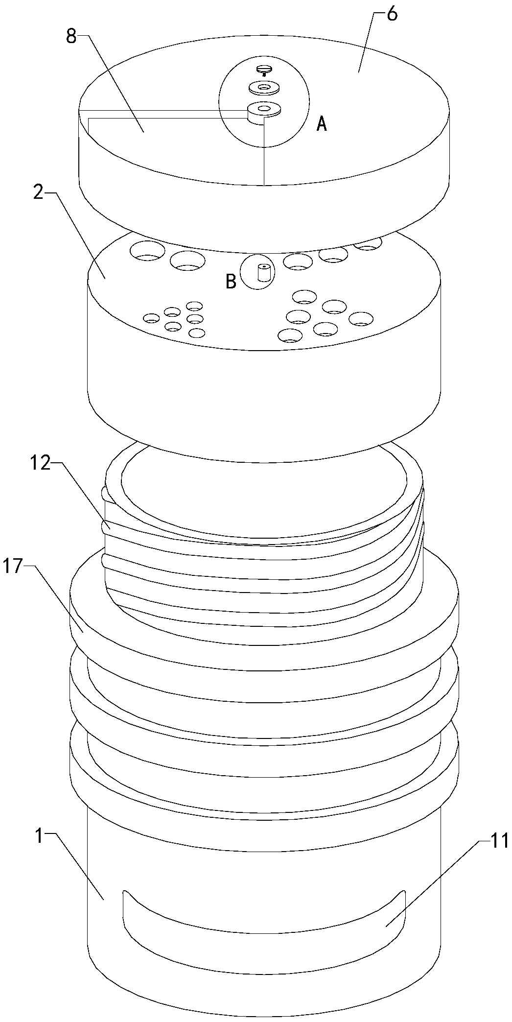
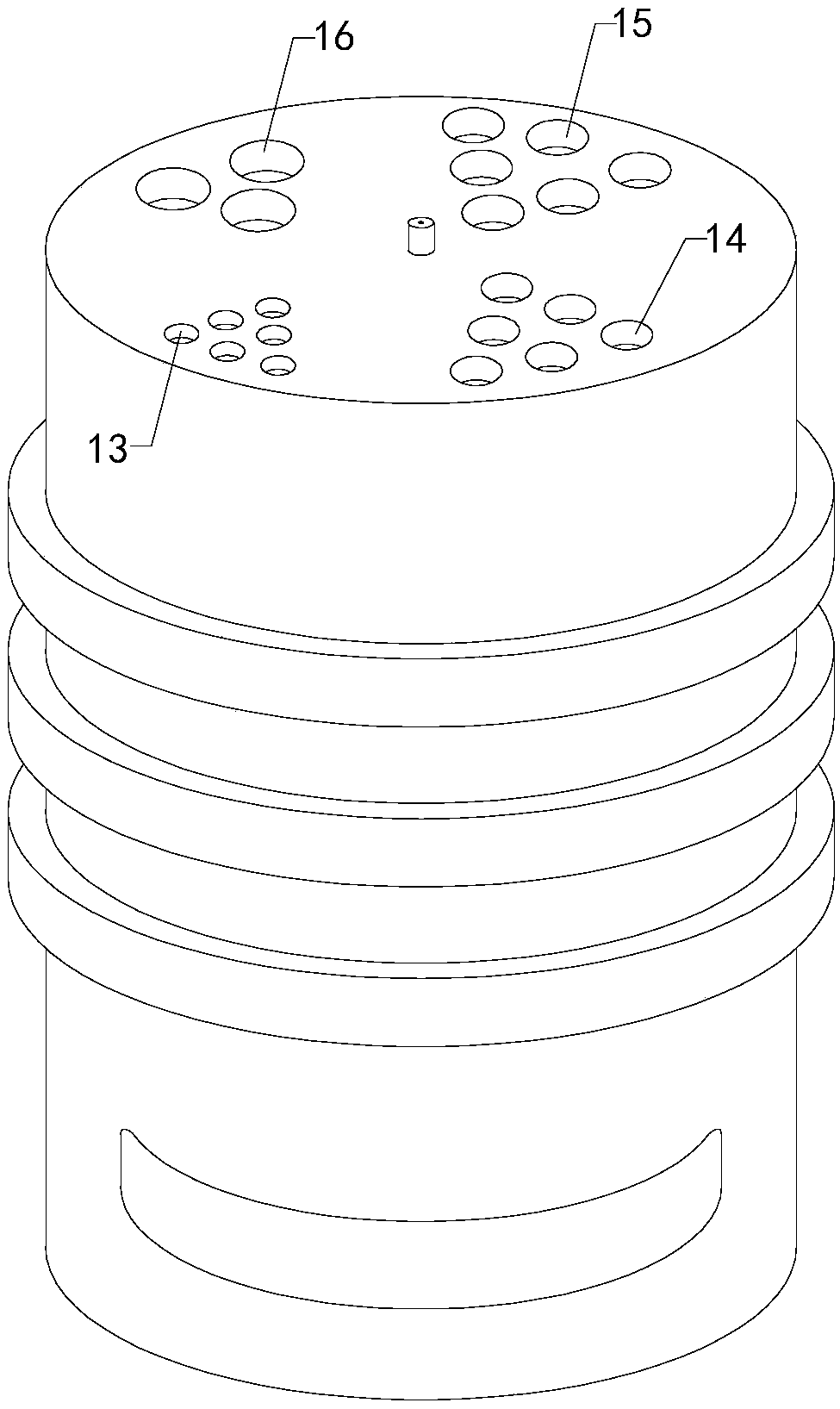
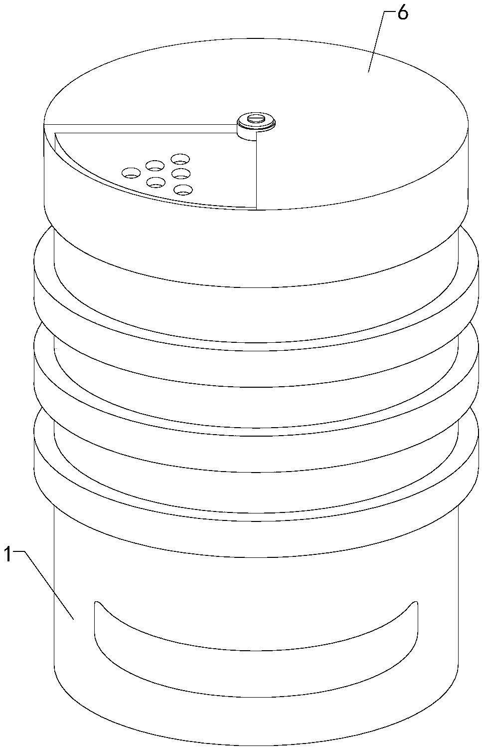
[0017] Such as Figure 1 to Figure 5 As shown, a controllable seasoning bottle of the present invention includes a cup body 1 and a cup cover 2. A placement cavity is arranged inside the cup body, and a pick-and-place opening is provided on the top of the cup body, and the pick-and-place mouth communicates with the inside of the placement cavity. , the bottom end of the cup cover is provided with a snap-in slot, and the cup cover is fastened on the upper part of the outer wall of the cup body through the snap-in slot, and the top inner wall of the cup cover is mounted on the pick-and-place opening; including the rotating shaft 3, the retaining plate 4, Fix the bolt 5 and ...


PUM


Abstract

The invention relates to the technical field of accessory devices for kitchen supplies, in particular to a seasoning bottle capable of controlling the dosage. The dosage of seasonings poured outside can be controlled by the bottle, and the using reliability is improved; the interior of the bottle can be observed, the types and dosage using conditions of the seasonings in a placing cavity can be timely known, and the using limit is lowered. The seasoning bottle comprises a cup body and a cup lid, the placing cavity is formed in the cup body, a taking and putting opening is formed in the top ofthe cup body and communicated with the interior of the placing cavity, a clamping groove is formed in the bottom of the cup lid, the cup lid is buckled on the upper portion of the outer side wall of the cup body through the clamping groove, and the inner wall of the top of the cup lid covers the taking and putting opening; the seasoning bottle comprises a rotary shaft, a stopping disc, a fixing bolt and a rotary lid; the seasoning bottle further comprises a transparent baffle, an observation window is formed in the lower side of the outer side wall of the front end of the cup body and communicated with the interior of the placing cavity, and the transparent baffle is fixedly installed on the observation window.

Description

technical field [0001] The invention relates to the technical field of accessories for kitchen supplies, in particular to a seasoning bottle with controllable volume. Background technique [0002] As we all know, the seasoning bottle is a kind of auxiliary device used for holding kitchen seasonings, so that it is easier to take and use during cooking, and it has been widely used in the field of kitchen supplies; The bottle includes a cup body and a cup cover. The inside of the cup body is provided with a placement cavity, and the top of the cup body is provided with a pick-and-place opening, which communicates with the inside of the placement cavity. The Tongka slot buckle is installed on the upper part of the outer wall of the cup body, and the top inner wall cover of the cup cover is installed on the pick-and-place opening; when the existing seasoning bottle is used, the seasoning is first placed in the placement cavity in advance, and it is directly taken out when in use....

Claims


Application Information

Patent Timeline
IPC IPC(8): A47J47/01A47J47/04
CPCA47J47/01A47J47/04
Inventor 鲍若妍
Owner 鲍若妍
Why Eureka
Try Eureka